
Tool Head with X-Axis Assembly Replacement Guide for the H3C
Bambu Lab H3C • Série Industrial H3
Tool Head with X-Axis Assembly Replacement Guide for the H3C
Tool Head with X-Axis Assembly
The Tool Head with X-Axis Assembly is a composite integrated accessory of the X-Axis and the toolhead. Specifically, the X-Axis is the guide rail along which the toolhead moves horizontally; the toolhead is a multi-functional core execution unit of the printer, integrating functions such as tool recognition and usage, intelligent control and detection, and airflow cooling.

When to Replace
Bambu Lab technical support has determined that the Tool Head with X-Axis Assembly needs to be replaced.
Safety Tips
Before performing any maintenance on the printer and its electronic components (including the Toolhead Cable), turn off the printer and disconnect the power supply to prevent accidental Screen touches or short circuits, which could cause additional electronic damage and safety hazards.

When performing maintenance or troubleshooting on your printer, please first check the temperature of the hotend and heatbed. Avoid operating at high temperatures. If operating at high temperatures is unavoidable, wear insulated gloves to ensure safe and effective maintenance.
Tools and Materials
- H2.0 allen key
- H1.5 Allen Key
Disassembly and Assembly Tips
Disassembly and assembly of the Tool Head with X-Axis Assembly requires removing the AMS 3H first. Please refer to the WIKI: AMS 3H Removal and Installation Guide to remove and reinstall the AMS 3H from the printer. All operations in this guide are performed with the AMS 3H removed.
Remove the Tool Head with X-Axis Assembly
Passo 1. Remove the Rear Panel
Refer to the dedicated Rear Panel Replacement Guide for the H3C, disconnect the power cable, and remove the rear panel.
Passo 2. Remove the Left and Right Side Windows
Please refer to the WIKI: Side Window Replacement Guide to remove the printer’s left and right side windows.
Passo 3. Disconnect the USB-C Cable from the AP
Please refer to the WIKI: AP Board Replacement Guide to remove the light guide plate and the USB-C cable management clip.

Disconnect the USB-C cable connector from the AP board and release the cable from the clip. Then, pull the USB-C cable connector out from the rear of the printer.
 |
 |
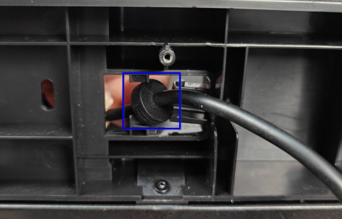
Pull the ferrite ring on the USB-C cable out of its slot, then use an allen key to pry the end of the Cable Chain upwards to release its lock and detach it. Adjust the angle of the ferrite ring so that it retracts into the printer cavity. This allows the USB-C cable and Cable Chain assembly to be completely removed from the printer.
 |
 |
Passo 4. Remove the XY Belts from the Toolhead Assembly
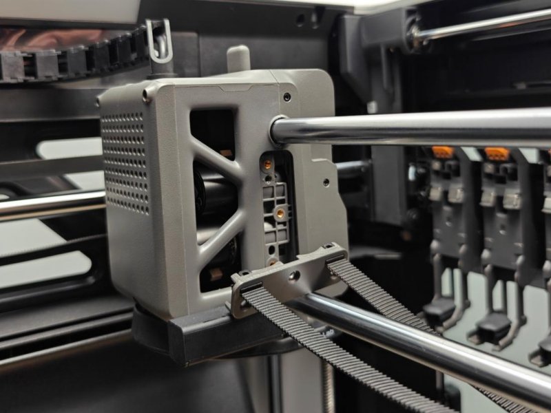
Using an H2.0 allen key, remove the 3 screws in the order indicated by the screw markings in the diagram to loosen the left XY belt fixing bracket.
 |
 |
Using an H1.5 allen key, pry out the tension block at the end of the belt, and then remove the fixing bracket.
 |
 |
From the X motor side, pull the XY belts to remove both belts from the Y carriage.
 |
 |
Follow the same procedure to remove the right XY belt from the toolhead and the Y carriage.
 |
 |
Warm Tip:
To prevent accidentally pulling the XY belts completely out of the print chamber during operation, which would require re-threading the belts from the rear, you can reattach the fixing bracket after loosening the XY belts from the Y carriage.

Passo 5. Remove the Tool Head with X-Axis Assembly
(The operation is the same for both left and right sides)
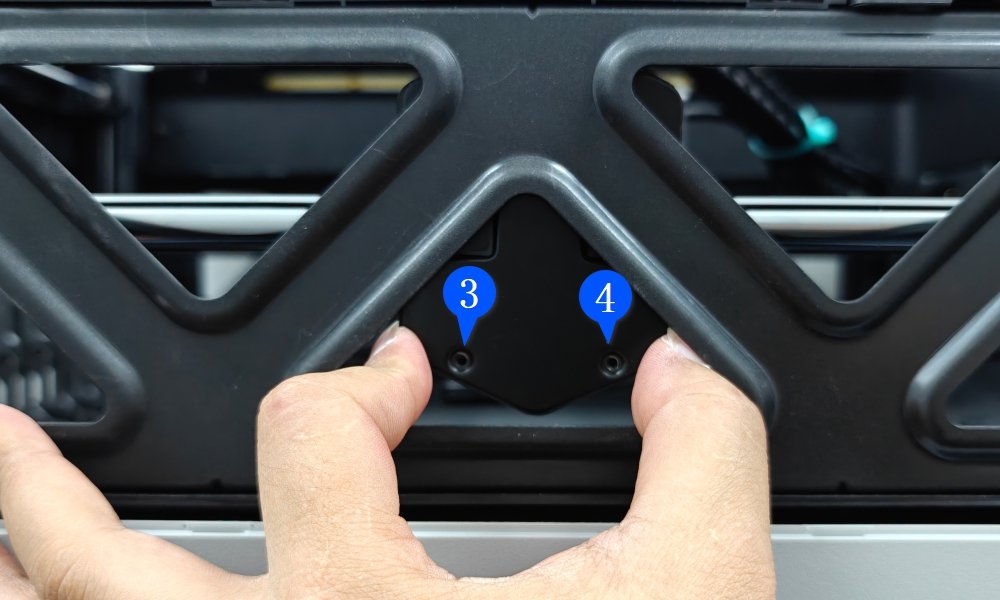
Shift the X-Axis forwards and backwards to expose the screws securing the metal cover plate. Using an H1.5 allen key, remove the 4 screws.
 |
 |
Move the X-Axis to fully expose the metal cover plate, then remove the metal cover plate from the underside of the Y linear shaft.
 |
 |
Repeat the same operation to remove the metal cover plate on the other side.
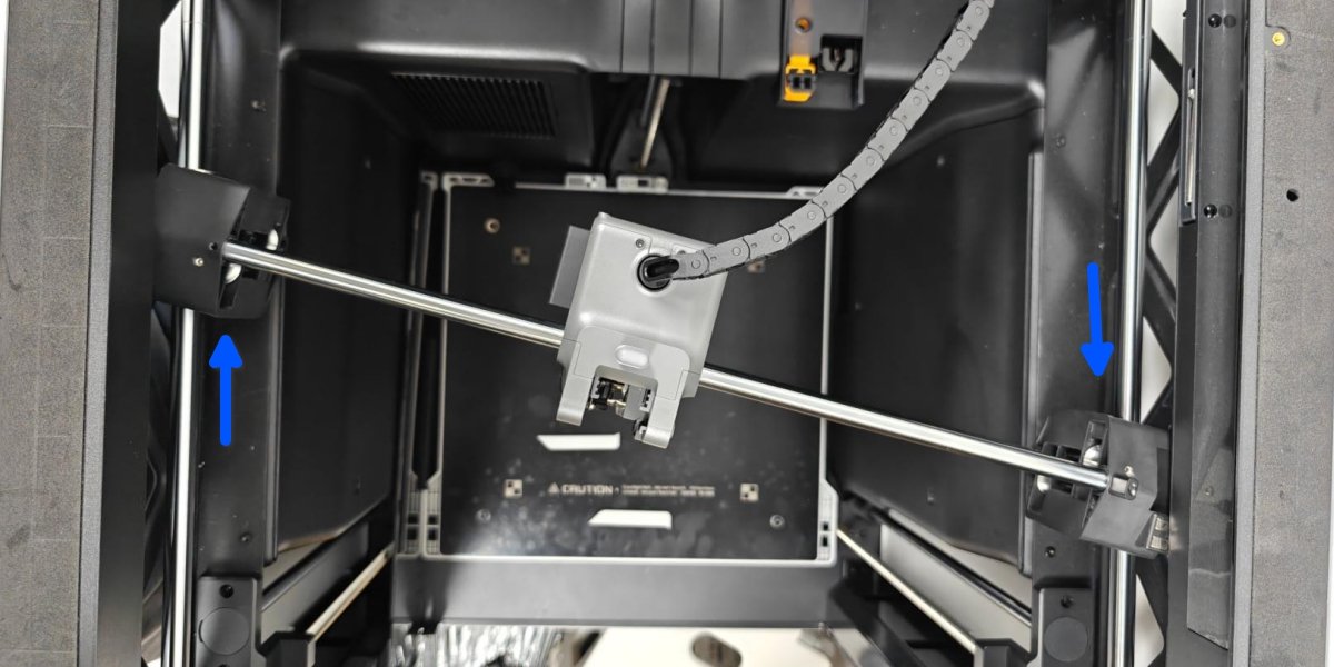
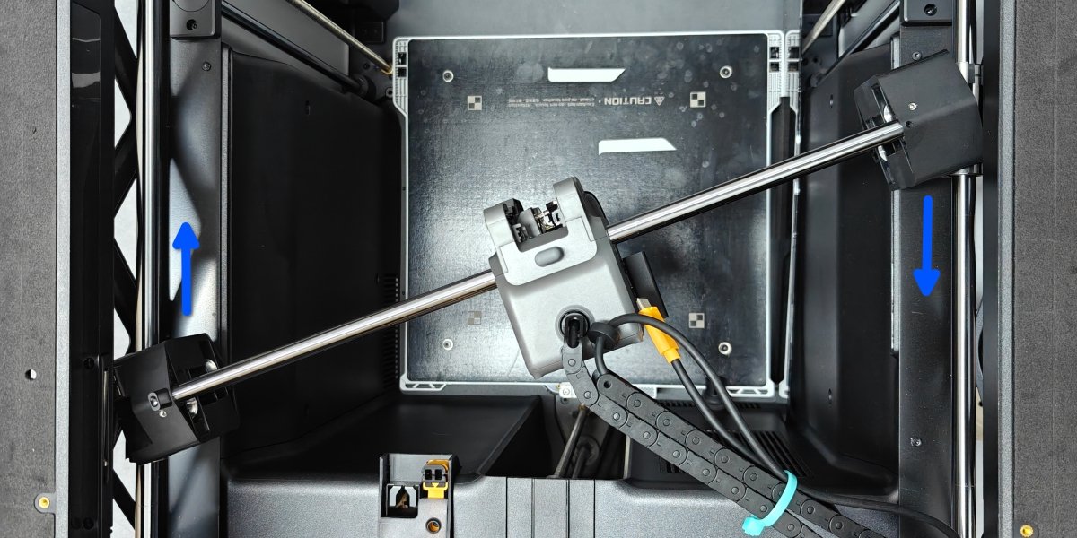
Then, move the Y carriages in opposite directions on both sides. The X-Axis will tilt and disengage from the Y bearings, allowing you to remove the Tool Head with X-Axis Assembly.
Install the Tool Head with X-Axis Assembly
Passo 1. Install the Tool Head with X-Axis Assembly
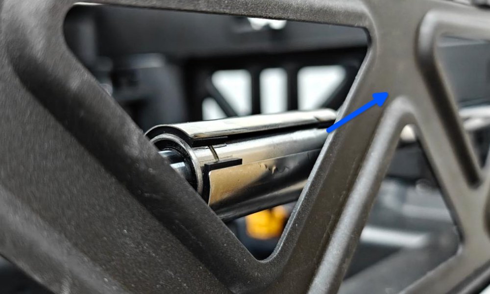
Manually adjust the position of the Y linear bearings so that the outer notch of the bearings is approximately 45 degrees outwards.
 |
 |
Then, place the Tool Head with X-Axis Assembly at a 45-degree angle to engage the carriage assembly. If the Y bearings have a very noticeable protruding part, you can lay an allen key horizontally to press it flat (fine-tuning will also be done when installing the metal cover plate later).
Check the letter markings on the metal cover plates to distinguish the installation positions: L for installation on the left side, and R for installation on the right side.

Place the right cover plate onto the crossbeam from the gap between the frame and the Y linear shaft. Ensure the letter marking is facing forwards.
 |
|
Then move the X-Axis and adjust its position to install the metal cover plate onto the carriage. Align the screw holes, and tighten the 4 screws to secure it. If the screw holes are not aligned and the hooks on the cover plate are caught on the Y bearings, you can move and adjust it.
 |
 |
Perform the same operation to install the metal cover plate on the other side.
Passo 2. Install the XY Belts Onto the Toolhead
(If you chose to secure the belts with a bracket when removing them earlier, please remove the bracket first.)
First, install the belts that need to pass through the front uprights (the upper belt on the left side, and the lower belt on the right side). The specific steps are as follows:
Passo 1. The belt passes directly through the through-hole on the Y-Axis;

Passo 2. Thread the belt from the outer side of the front idler pulley and out through the inner side. After it passes through, use your other hand to pull the belt towards the Y carriage;
 |
 |
Tip: If there is resistance when threading the belt, you can move your hand closer to the idler pulley and push harder, or slightly bend the belt along its back before threading it.
Passo 3. Thread the belt onto the Y carriage again, but it needs to be folded towards the toolhead. To prevent the belt from passing directly through the Y carriage, you can use another belt to temporarily block the Y carriage by threading it through first, and use it as a guide belt to assist in threading.
 |
 |
Passo 4. Thread the other belt from the other idler pulley position, with the belt folded towards the toolhead first.

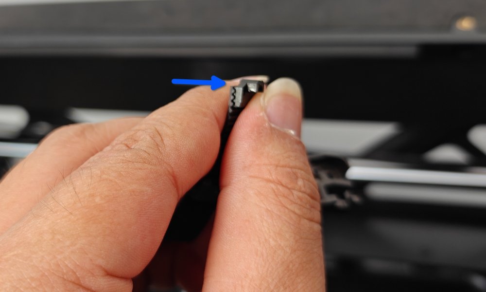
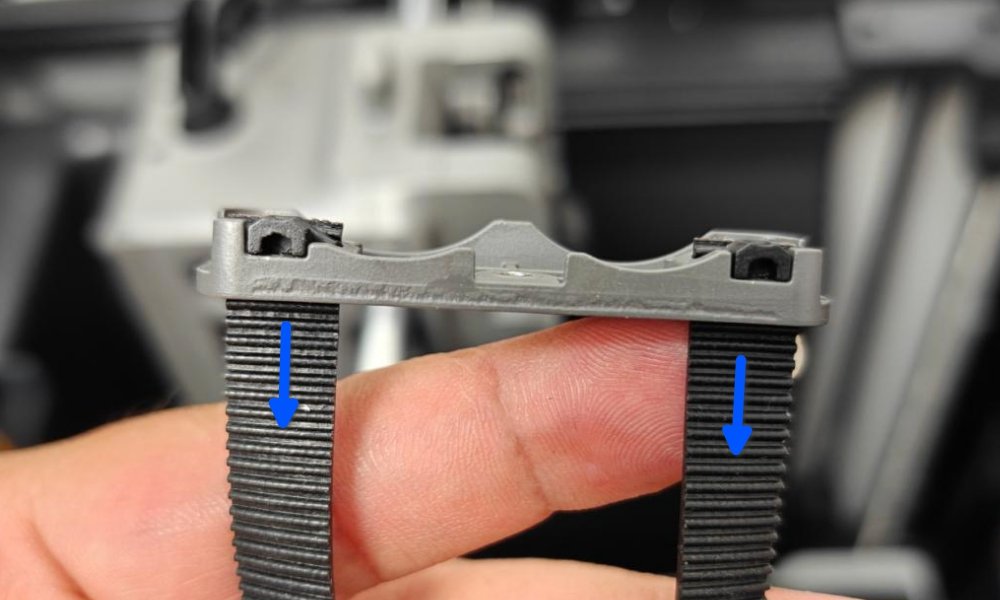
After both belts have passed through the Y carriage, you can thread the belts onto the fixing bracket and press them tight with the tension block. Pulling the belt in the opposite direction can help the tension block secure the belt more effectively.
 |
 |
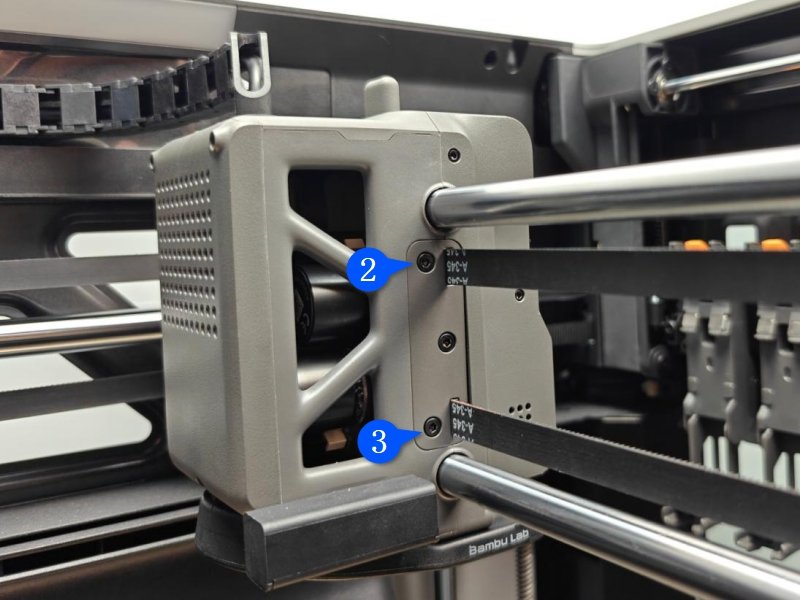
Install the XY belt fixing bracket onto the toolhead. Press and hold the fixing bracket with your hand, first tighten the 1 screw in the middle position, and then tighten the 2 upper and lower screws.
 |
 |
Using similar steps, install the belt on the other side and secure it to the toolhead.
Warm Tip:
If it is difficult to secure the belt bracket, you can refer to the following steps to first compress the XY tensioners.
Use a wrench to push the tensioner and compress the tension spring, then tighten the two tension screws. This will place the tensioner in a state of maximum compression.
 |
 |
Passo 3. Connect the USB-C Cable to the AP Board
Pass the USB-C cable connector through the cable hole on the printer’s Top Lid assembly, and route it through the rear-left pillar to the AP board area.
 |
 |
Clip the USB-C cable into the end of the cable chain, then install the end of the cable chain onto the printer and insert the ferrite ring into the mounting slot.
 |
 |
Then, refer to wiki: AP Board Replacement Guide Steps 2 & 3 for installation procedures, connect the USB-C cable, and install the light guide plate.

Passo 4. Tension the XY Belts
Loosen the screws of both the left and right XY tensioners (if the tensioners were manually compressed when installing the XY belts earlier). Allow the tensioners to naturally tension themselves. Move the toolhead back and forth 2-3 times, then re-tighten the tensioner screws.

Passo 5. Install the Back Panel (install After Inspection)
Refer to the dedicated Rear Panel Replacement Guide for the H3C to install the rear panel and other accessories.
Passo 6. Install the Left and Right Side Windows (install After Inspection)
Please refer to the WIKI: Side Window Replacement Guide to install the printer’s left and right side windows.
Verify Functionality
Connect the power and turn on the printer. Start a print job; if no errors occur, the installation is successful.
Notas Finais
We hope this guide has provided clear and practical support.
If the issue remains unresolved, please submit a support ticket and include your recent printer logs and additional pictures or other details. Our customer support team will review your request and provide detailed assistance.
You can also visit Bambu AI, which can instantly answer common questions and provide you with operational guidance.


