
Toolhead Board Replacement Guide for the X2D
Bambu Lab X2D • Série Avançada X2
Toolhead Board Replacement Guide for the X2D
Toolhead Board
🔎 Find the X2D TH Board, X2D Extruder Connection Board, and the X2D Hotend Heating Assembly Connection Board in the Bambu Lab store.
The toolhead circuit board refers to:
- TH board (extruder mainboard): a circuit board that implements the electrical control of filament extrusion-related actions on the printer, such as loading/unloading filament, retraction, temperature adjustment, etc.
- Toolhead Interface Board: a circuit board providing interfaces to connect the extruder, filament sensor board, Eddy Current Coils, and toolhead front shell components;
- Hotend Heating Assembly Interface Board: a circuit board that provides the interface for the hotend heating assembly.


There are both black and silver versions of the heatsink on the TH board.The picture below is the TH Board with silver heatsink.

Applicable printer model
Bambu Lab X2D
When to Replace
- Components, connectors, or cables on the circuit board are clearly damaged, affecting their usability.
- After an exchange inspection or tool measurement, it is confirmed that the fault is caused by the relevant accessories.
- Bambu Lab technical support has confirmed that the TH board, Toolhead Interface Board, or Hotend Heating Assembly Interface Board needs to be replaced.
Required tools and materials
- H1.5 Screwdriver
- Tweezers
Aviso de Segurança
⚠️ IMPORTANT!
It’s crucial to power off the printer before conducting any maintenance work, including work on the printer’s electronics and tool head wires. Performing tasks with the printer on can result in a short circuit, leading to electronic damage and safety hazards.
During maintenance or troubleshooting, you may need to disassemble parts, including the hotend. This exposes wires and electrical components that could short circuit if they contact each other, other metal, or electronic components while the printer is still on. This can result in damage to the printer’s electronics and additional issues.
Therefore, it’s crucial to turn off the printer and disconnect it from the power source before conducting any maintenance. This prevents short circuits or damage to the printer’s electronics, ensuring safe and effective maintenance. For any concerns or questions about following this guide, we recommend submitting a chamado técnico relatando o seu problema. and we will do our best to respond promptly and provide the assistance you need.
Video Guide
Remove the Toolhead Circuit Board
Passo 1. Remove the Toolhead Cover
Please refer to Toolhead Housing Replacement Guide for the X2D to remove the toolhead shell.
Passo 2. Remove the TH Board (Extruder Mainboard)
Use tweezers to sequentially disconnect the cables connected to the TH board (extruder mainboard), including the Hotend Heating Assembly Connection Board cable 1 , Extruder Connection Board cable 2 , Extruder Motor cable 3 , Toolhead Camera cable 4 , Right Hotend Cooling Fan cable 5 , Flow Blocker Assembly cable 6 , Left Hotend Cooling Fan cable 7 .

Use an H1.5 allen key to remove the four screws securing the TH board (extruder mainboard) one by one, then loosen the TH board.

Unplug the toolhead cable and remove the TH board (extruder mainboard).

Passo 3. Remove the reinforcement bracket
Remove the screw on the right side of the cutter assembly, then lift the lever to the right as shown.

Remove the screw on the left side of the cutter assembly, then lift the lever to the left as shown.

Use an H1.5 allen key to remove the two screws on the bracket of the hotend heating interface board.

Remove the reinforcement bracket of the hotend heating interface board.

Passo 4. Remove the Toolhead Interface Board
Tear off the wiring foam.

Sequentially disconnect the connections of the left Eddy Current Sensor 1 , left Extruder Filament Sensor 2 , right Extruder Filament Sensor 3 , and right Eddy Current Sensor 4 .
| No. | 1 | 2 | 3 | 4 |
|---|---|---|---|---|
| Interface Description | Eddy Current Sensor – Left | Extruder Filament Sensor – Left | Extruder Filament Sensor – Right | Eddy Current Sensor – Right |
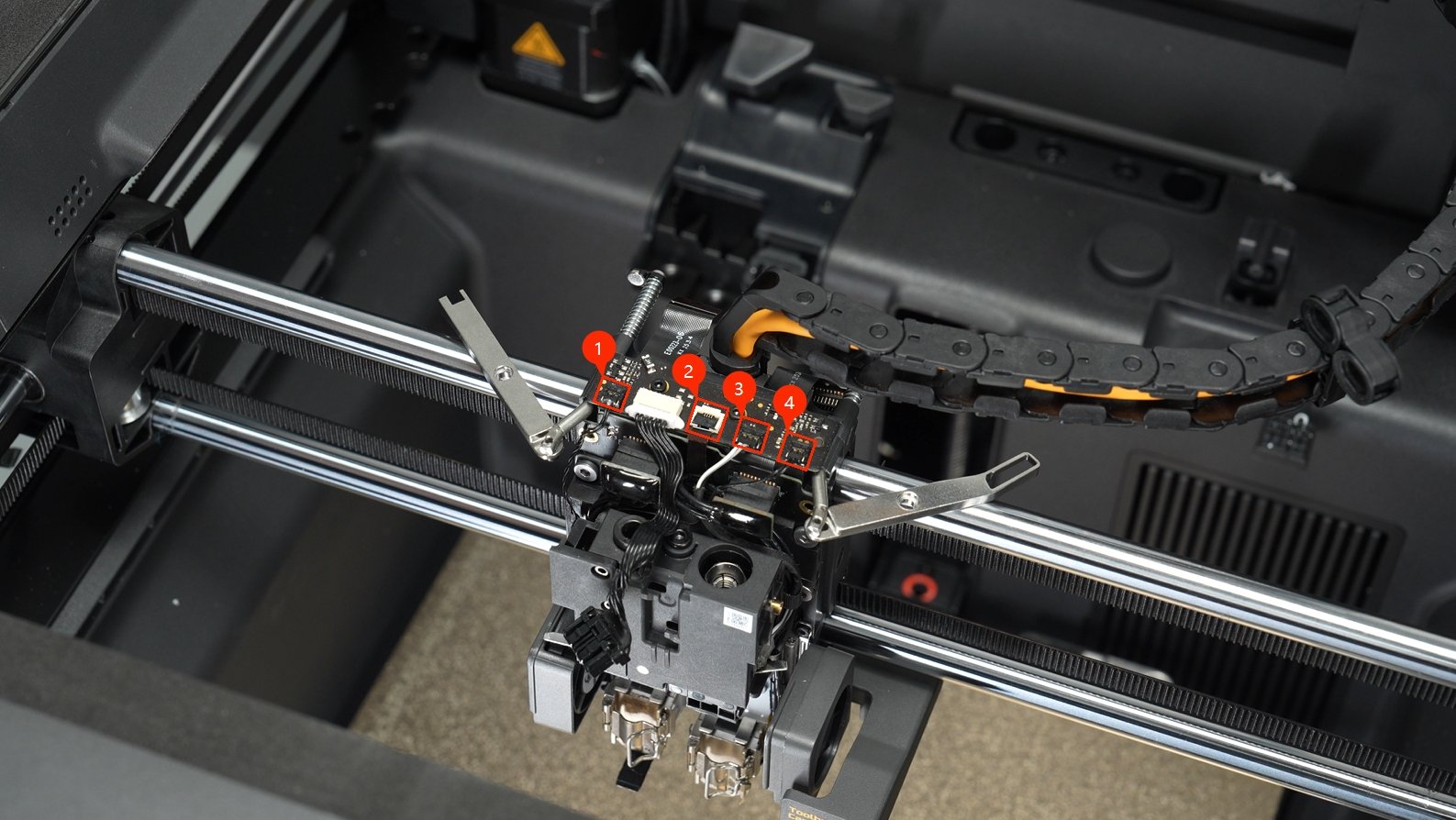
- Eddy Current Sensor 1 4 Disconnect it as shown below.
 |
 |
- Extruder Filament Sensor 2 3 Disconnect it as shown below. The left connector is a Flip-type FPC Connector. Removal method: Lift the black pressure block on top, then gently pull out the cable.
 |
 |
Use an H1.5 allen key to remove two screws and take off the toolhead interface board.

Use tweezers to remove the white glue on the toolhead interface board and detach the Logo LED cable.

Passo 5. Remove the Hotend Heating Assembly Interface Board
Disconnect the left hotend heating assembly and auxiliary hotend heating assembly cables from the hotend heating interface board.

Remove the hotend heating assembly interface board.

Install the New Toolhead Circuit Board
Passo 1. Install the Hotend Heating Interface Board
Install the hotend heating assembly interface board above the extruder. Please ensure that no cables are pinched between the interface board and the toolhead block to avoid issues during subsequent installation.
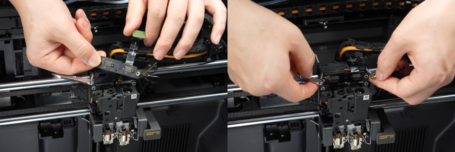
Connect the cables of the left hotend heating assembly and right auxiliary hotend heating assembly to the hotend heating assembly interface board respectively;

Passo 2. Install the Toolhead Interface Board
Install the Logo LED cable onto the toolhead interface board.

Install the toolhead interface board directly above the toolhead block. Be careful not to pinch the cable of the hotend heating interface board.

Use an H1.5 allen key to secure the two screws.
Connect the cables of the left Eddy Current Coil, left filament sensor board, right filament sensor board, and right Eddy Current Coil to the toolhead interface board sequentially.
Passo 3. Install the reinforcement bracket
Place the reinforcement bracket of the hotend heating interface board into position. Make sure the cables are inserted between the left and right hotend heating assemblies and pressed behind the bracket.

Use an H1.5 allen key to tighten the two screws of the hotend heating interface board bracket.
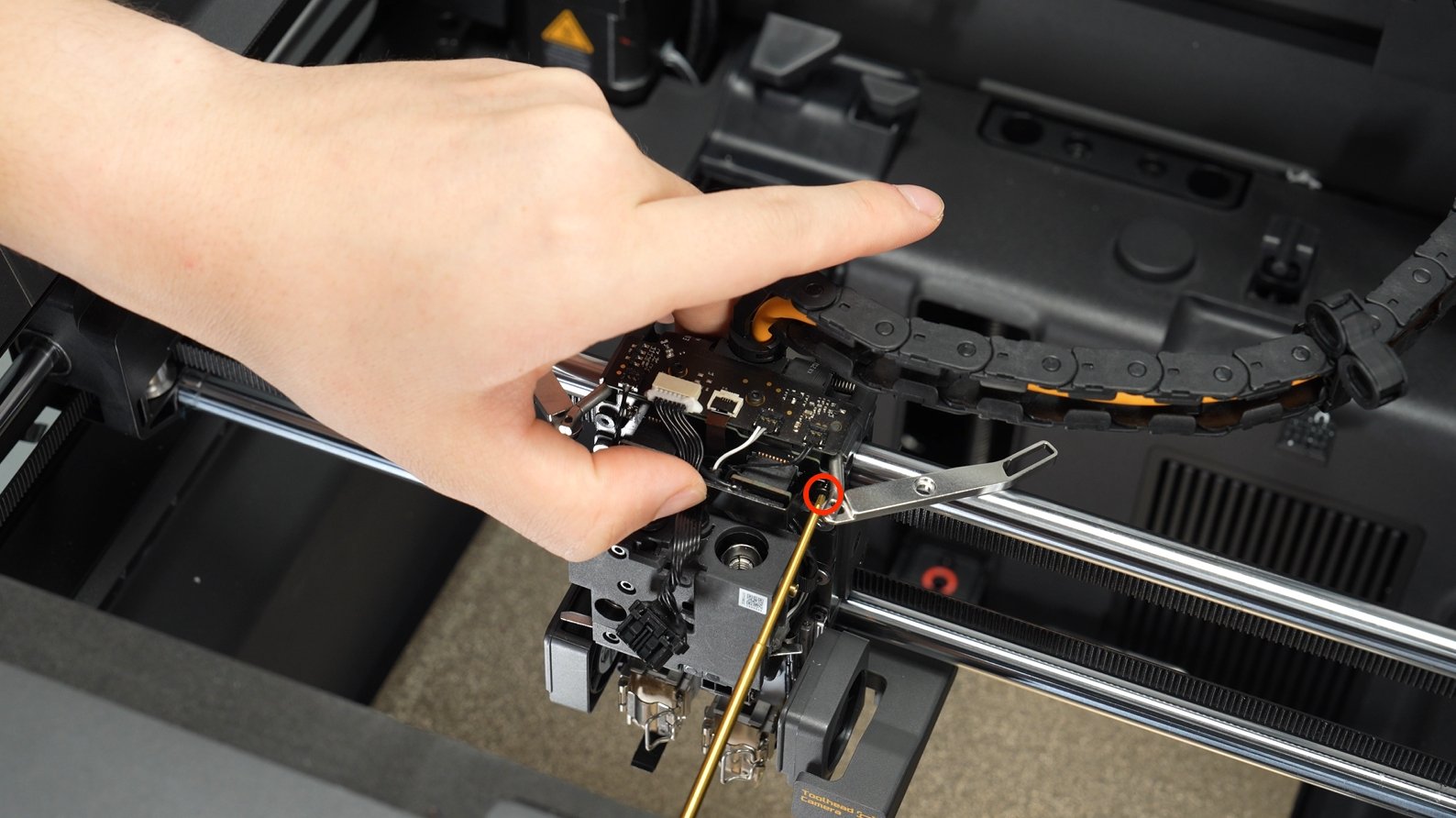

Reattach the protective foam.
Passo 4. Install the TH Board (Extruder Mainboard)
Connect the toolhead cable to the interface of the TH board (extruder mainboard) and secure the toolhead cable properly.

Align the TH board (extruder mainboard) with the screw positioning posts and use an H1.5 allen key to tighten the four screws, securing the TH board (extruder mainboard) to the back of the toolhead block.
Sequentially connect the Hotend Heating Assembly Connection Board cable 1 , Extruder Connection Board cable 2 , Extruder Motor cable 3 , Toolhead Camera cable 4 , Right Hotend Cooling Fan cable 5 , Flow Blocker Assembly cable 6 , Left Hotend Cooling Fan cable 7 .
| No. | Interface Description | No. | Interface Description | No. | Interface Description |
|---|---|---|---|---|---|
| 1 | Hotend Heating Assembly Connection Board | 4 | Toolhead Camera | 7 | Cooling Fan for Hotend – Left |
| 2 | Extruder Connection Board | 5 | Cooling Fan for Hotend – Right | ||
| 3 | Extruder Servo Motor | 6 | Flow Blocker Assembly |
Passo 5. Install Cutter Lever Assemblies
Restore the left and right cutter lever assemblies.
 |
 |
Please ensure that the notch at the lower end of the cutter lever correctly engages with the cutter assembly handle; otherwise, the lever assembly will not drive the handle to cut filament.

Passo 6. Install the Toolhead Shell
Refer to Toolhead Housing Replacement Guide for the X2D to install the toolhead shell.
Verifying Success
✅ Connect power, turn on the printer, perform calibration, and verify that calibration completes successfully.
- If you encounter any issues, please retrace your steps and check all connections before trying again.If the problems persist, please contact the Bambu Lab service team for further assistance.
Notas Finais
We hope this guide has provided clear and practical support.
If the issue remains unresolved, please submit a support ticket and include your recent printer logs and additional pictures or other details. Our technical team will review your request and provide detailed assistance.
You can also visit Bambu AI, which can instantly answer common questions and provide you with operational guidance.


