
Touchscreen FPC Cable Replacement Guide for the P2S/X2D
Bambu Lab P2S • Série Performance P2
Touchscreen FPC Cable Replacement Guide for the P2S/X2D
Touchscreen FPC cable
The 5-inch touch screen at the front of the P2S is connected to the AP board via a Flexible Printed Circuit (FPC) ribbon cable.

When to Use This Guide
The FPC cable which connects the screen and AP board is damaged.
Required Tools and Materials
- A new screen FPC cable
Aviso de Segurança
IMPORTANT!
Always power off and disconnect power on the printer before performing maintenance work. Not doing so means there is a risk of electric shock, short circuit, and damage to the printer or surrounding area.
When a maintenance task necessitates the printer being powered on, use insulated gloves for safety and pay special care not to pinch, damage, or put pressure on any exposed wires, connectors, or circuit boards. Additionally, the nozzle can be extremely hot so never touch it with exposed skin.
If you have any questions or concerns related to the above or the steps in this guide, please open a new ticket in our Support Page for assistance.
Removing the Touchscreen Cable
Passo 1: Remove the Screen
First, refer to the Screen Replacement Guide wiki page to remove the screen.

Passo 2: Remove the Cable
Open the AP cover front section, then unlock the screen FPC cable lock on the AP board to disconnect the cable from the AP board.

Remove the old ribbon cable from the AP board connector.

Pull the cable from the side that connects to the screen, guiding the other end to fit through the slot until the entire cable is free.

Installing the Touchscreen Cable
Passo 1: Install the Screen Line
Fit the thin end of the cable through the screen cable slot and route it toward the AP board, leaving the thicker metal connector near where the screen is installed.
The cable must take a sharp turn toward the AP board once inserted through the slot in the front.
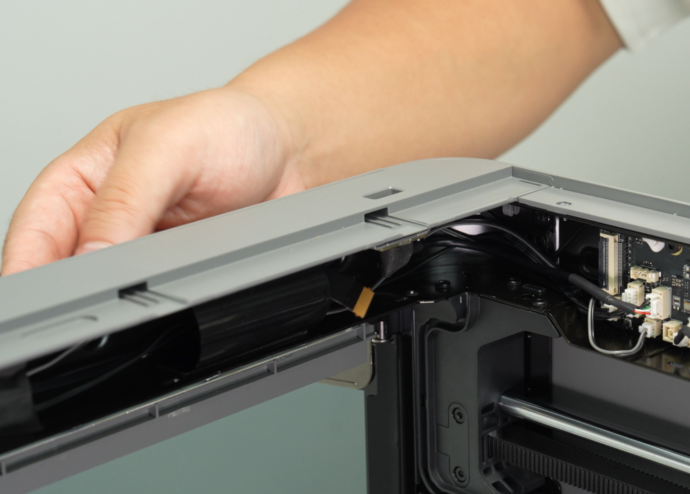
Align the thin connector end of the screen cable with the socket on the AP board, careful to insert it straight and centered in the socket with the locking buckle.
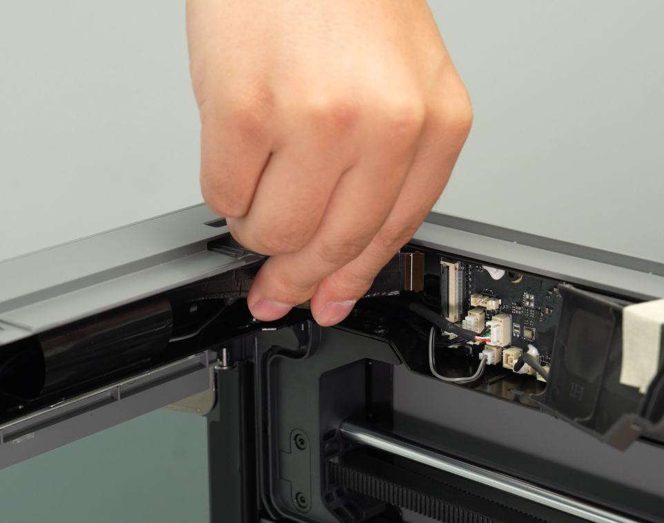
Lock the buckle over the inserted cable, avoiding using too much force and ensuring that the cable is inserted fully and aligned properly.

Be sure to route the screen cable behind the USB port component hanging from the top of the printer’s frame near the corner.
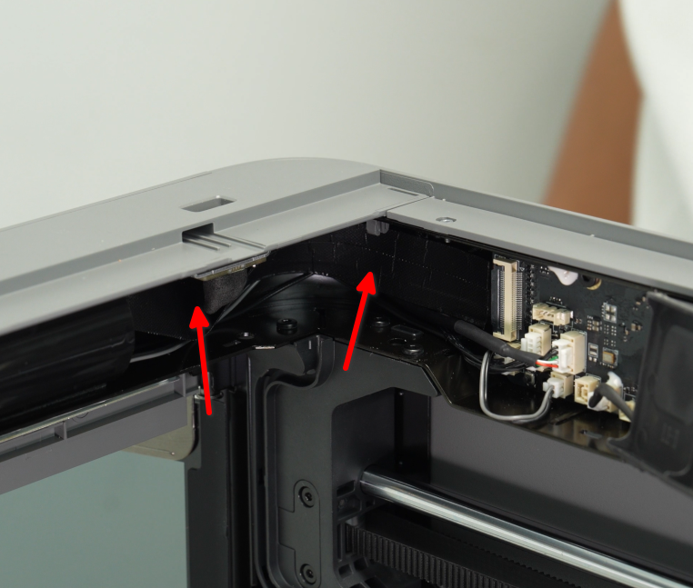
Passo 2: Install the Screen
Refer to the Screen Replacement Guide wiki page to reinstall the screen.
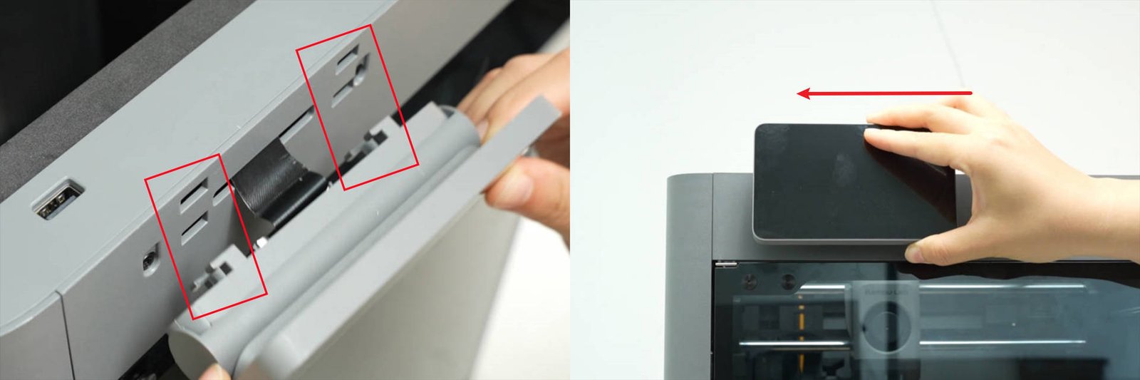
Verifying Functionality
Connect the power supply and turn on the printer to check whether the screen displays correctly and registers touch input normally.
Notas Finais
We hope this guide has provided clear and practical support.
If the issue remains unresolved, please submit a support ticket and include your recent printer logs and additional pictures or other details. Our technical team will review your request and provide detailed assistance.
You can also visit Bambu AI, which can instantly answer common questions and provide you with operational guidance.


