
Toolhead Circuit Board Replacement Guide for the P2S
Bambu Lab P2S • Série Performance P2
Toolhead Circuit Board Replacement Guide for the P2S
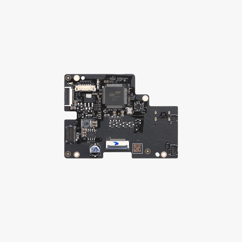
TH Board/Extrusion Interface Board/TH Board FPC Cable
Since the replacement of the TH board, extrusion interface board, and TH board FPC cable are closely related, we have written this replacement guide in the same Wiki. You can replace the corresponding spare parts according to your actual needs.
TH Board:
A circuit board that implements the associated actions of the printer’s filament extrusion (such as feeding, withdrawing, retraction, temperature adjustment, etc.).
The accessory package includes the TH board and fixing screws:
- TH board* 1
- BT2x5 screw* 4
Extrusion Interface Board:
This circuit board connects the extruder and the component cooling fan interface.
The accessory package includes the extrusion interface board and its fixing screws:
- Extrusion interface board* 1
- BT2x5 screw* 2
TH Board FPC Cable:
A flexible cable that connects the TH board to the extrusion interface board.
Only one TH board FPC cable is included in the accessory package.


When to Use This Guide
- Components, connectors, or cables on the circuit board are clearly damaged, affecting their usability.
- After an exchange inspection or tool measurement, it is confirmed that the fault is caused by the relevant accessories.
- Bambu Lab technical support has confirmed that the TH board, extrusion interface board, or TH board FPC cable needs to be replaced.
Required Tools and Materials
- New parts that need to be replaced
- H1.5 Allen key
- Tweezers
Aviso de Segurança
IMPORTANT!
Always power off and disconnect power on the printer before performing maintenance work. Not doing so means there is a risk of electric shock, short circuit, and damage to the printer or surrounding area.
When a maintenance task necessitates the printer being powered on, use insulated gloves for safety and pay special care not to pinch, damage, or put pressure on any exposed wires, connectors, or circuit boards. Additionally, the nozzle can be extremely hot so never touch it with exposed skin.
If you have any questions or concerns related to the above or the steps in this guide, please open a new ticket in our Support Page for assistance.
TH board connector

| NO. | Connection components |
|---|---|
| 1 | Hotend Heating Assembly |
| 2 | TH Board FPC Cable |
| 3 | 3508 Extruder Servo Motor |
| 4 | Cooling Fan for Hotend |
| 5 | Eddy Sensor |
| 6 | Toolhead Cable |
Removing the Toolhead Circuit Board
Passo 1: Remove the Toolhead Housing
Please refer to the wiki page Replacing the Toolhead Housing to remove the toolhead housing.

Passo 2: Remove the TH Board
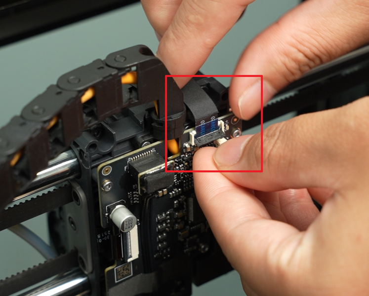
Open the connectors of the TH board FPC cable and the extrusion motor cable, then disconnect the cables.
 |
 |
Remove the foam and tape from the TH board one by one, then disconnect the hot-end heating assembly, hot-end cooling fan, and eddy-current coil. When disconnecting the hot-end fan and eddy-current coil cables, pull them perpendicular to the connector. Do not apply force or shake them left or right to avoid damaging them.
 |
 |

Use an H1.5 Allen key to remove the four screws (BT2x5), unlock the TH plate, pull out the tool head cable, and then remove the TH plate.
 |
 |
Passo 3: Remove the extruder Interface Board and TH Board FPC Cable
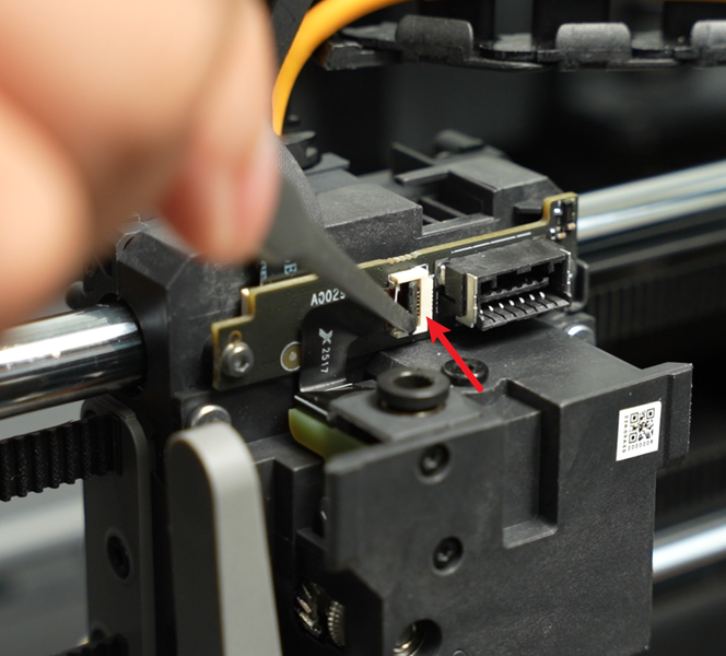
Open the cover of the Hall switch board assembly connector and disconnect the Hall switch board cable.
 |
 |
Note: Some machines have black glue applied to the connector. Use tweezers to remove it and then open the connector. No additional glue is required when reconnecting.
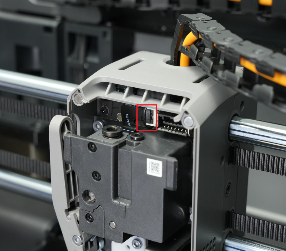
Use an H1.5 Allen key to remove the two screws (BT2x5) securing the extrusion interface board, then remove the extrusion interface board.
 |
 |
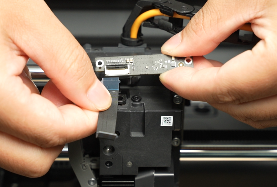
Open the connector tab on the back of the extrusion interface board and remove the TH Board FPC Cable.
 |
 |
Installing the Toolhead Circuit Board
Passo 1: Connect the TH Board FPC Cable
Connect the TH board FPC cable to the connector on the back of the extrusion interface board and snap the cover on.
 |
 |
Passo 2: Install the Extrusion Interface Board
Install the extrusion interface board above the extruder and tighten the two fixing screws (BT2x5) using an H1.5 Allen wrench.
|
|
Connect the Hall switch board cable to the connector on the extrusion interface board and secure the cover.
 |
|
Passo 3: Install TH board
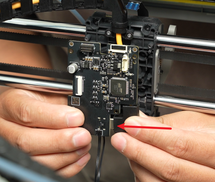
Connect the toolhead cable to the connector on the back of the TH board, then install it on the back of the toolhead. Note: The toolhead cable needs to be clipped between the two cable clips. The routing of the toolhead cable is shown in red.
 |
 |
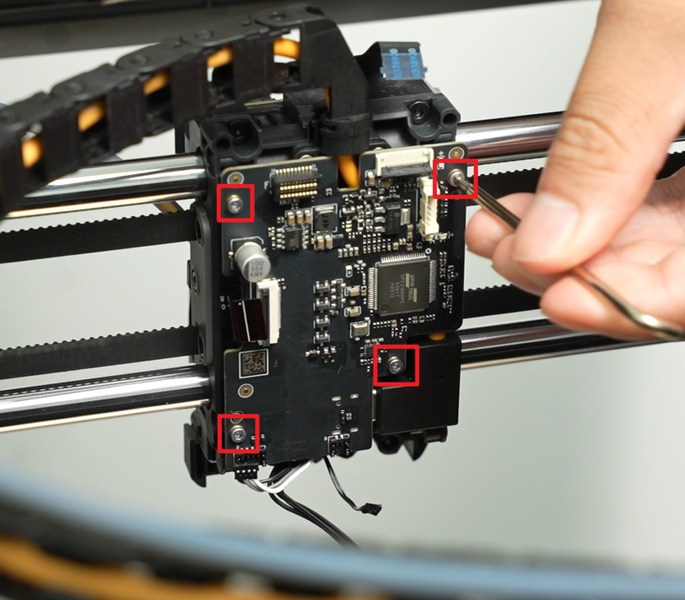
Use an H1.5 Allen key to tighten the four TH plate fixing screws (BT2x5).
Connect the cables from the eddy current coil to the hot end fan, ensuring they are aligned and fully inserted into the connector.
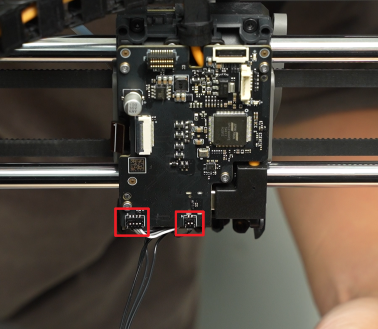
Connect the hot end heating element cable and reattach the foam and tape.
 |
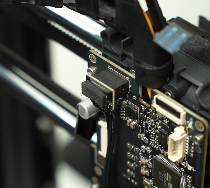 |

Connect the extrusion motor cable and the TH board FPC cable respectively, then fasten the cover.
 |
 |
Passo 4: Install the Toolhead housing
Refer to the instructions for “replacing the Tool Head Housing” to install the toolhead housing.

Verifying Functionality
Connect the power supply, turn on the printer, perform the calibration operation, and confirm that the calibration operation passes normally.
If you encounter any problems, please retrace your steps and check all connections before trying again. If the problem persists, please contact Bambu Lab technical support team for further assistance.
Notas Finais
We hope this guide has provided clear and practical support.
If the issue remains unresolved, please submit a support ticket and include your recent printer logs and additional pictures or other details. Our technical team will review your request and provide detailed assistance.
You can also visit Bambu AI, which can instantly answer common questions and provide you with operational guidance.


