
AC Board Replacement Guide – A1
Bambu Lab A1 • Série Bed-Slinger A1
AC Board Replacement Guide – A1
In this guide we will show the process of replacing the AC Board on the A1
- The A1 AC board is available in two versions. Both versions function identically, the difference is due to a minor update. The same documentation on the wiki applies to both.

When to use?
This guide should be used if the AC Board of the A1 is faulty, and needs to be replaced.
Common issues that are caused by the A1 AC Board are:
- Heatbed is not heating
- Recommended by Bambu Lab customer support
Tools and materials needed
Bambu Lab AC Board for A1
- H2.0 hex wrench
- 20-30 minutes
Aviso de Segurança
IMPORTANT!
It’s crucial to power off the printer before performing any maintenance work on the printer and its electronics, including tool head wires, because leaving the printer on while conducting such tasks can cause a short circuit, which can lead to additional electronic damage and safety hazards.
When you perform maintenane or troubleshooting on the printer, you may be required to disassemble some parts, including the hotend. This process can expose wires and electrical components that could potentially short circuit if they come into contact with each other or with other metal or electronic components while the printer is still on. This can damage the electronics of the printer and cause further damage.
Therefore, it’s essential to switch off the printer and disconnect it from the power source before doing any maintenance work. This will prevent any short circuits or damage to the printer’s electronics. By doing so, you can avoid potential damage to the printer’s electronic components and ensure that the maintenance work is performed safely and effectively.
If you have any concerns or questions about following this guide, open a new ticket in our Support Page and we will do our best to respond promptly and provide you with the assistance you need.
Steps to remove the old AC Board
1. Place the printer on its front
For easy access to the bottom section of the A1, you need to place the printer on the front.
Start by flipping the screen on its side, then gently place the printer on its front, as shown in the image below.
Use a box of filament to keep the top side raised to avoid putting pressure on the extruder and the screen.

2. Remove the Cable Box
Loosen but do not fully remove the screws marked in yellow. Disconnect the three cables (1, 2, 3) which are for the camera, Z-axis motor, and X-axis motor respectively. Then push the cable bracket upwards to disconnect the USB-C cable.

Note: If the cable bracket cannot be removed easily, you can fully remove the screws marked in yellow and try again.
3. Remove the Printer Bottom Cover
Remove the 10 screws marked in red on the bottom housing cover. Gently pry open the bottom housing cover to remove it.

4. Remove the heatbed power wires
In the next step, remove the two Heatbed power wires. Gently press on the sides of the connectors to release the security clip so you can disconnect the wires.
 |
 |
5. Remove the Heatbed Signal Cable connector
Carefully remove the Heatbed signal cable connector. A tool can be used to remove it, or you can simply grab the plastic connector and gently pull it out.
Avoid pulling from the wires as it can lead to damaging the wires or the connector.

6. Disconnect the ribbon cable
To disconnect the ribbon cable, simply raise the black plastic latch then gently pull the ribbon cable towards you.

7. Remove the remaining wire connectors from the AC board
Continue to remove the remaining cables. First, remove cables #1, #2, and #3, which are the ground wire, live wire, and neutral wire respectively. Pull the blue rubber sleeve outward, then use a screwdriver to press against the locking tab while pulling the cable outward. The #4 and #5 cables of the internal power supply will be removed later.
 |
 |
Note: The new version A1 power switch has removed the AC board ground wire, which optimizes the power switch structure and current-carrying capacity; this change does not affect the core functionality and performance of the AC board.
 old version
 new version
8. Take out the Old AC Board
Remove the fixing screw in the middle of the AC board, then release the plastic locking tabs to take out the AC board.

At this point, continue to remove the #4 and #5 cables of the internal power supply. If the cable is difficult to unlock, you can also use a screwdriver to pry it out directly.

Steps to Install the new AC Board
1. Transfer the insulating material to the new AC board
The old AC board has a black plastic insulating material applied to the board. Simply remove it from the old board, and transfer it to the new one as shown in the image below.

2. Screw in the new AC board
Carefully align the new AC board to the frame of the printer, then install the screw holding the board in place.
3. Re-connect the ribbon cable
Start by opening the black plastic clip of the ribbon cable, then gently insert the ribbon cable in it while aligning it to the white plastic tabs.
Once aligned, simply raise the black plastic clip to lock the ribbon cable in place.
Ensure that the blue strip on the ribbon cable is parallel to the black plastic connector, as shown in the image below.

4. Re-connect the Heatbed signal cable
Carefully align the white plastic connector as shown in the image below, and re-connect it to the AC board.
5. Re-connect the heatbed power cables
In the next step, carefully re-connect the heatbed power cables, as shown in the image.
The two plugs of the heatbed power cable have no specific installation order and color; just ensure they are correctly positioned on the motherboard.

6. Re-connect the remaining wires
Complete the AC board installation by connecting the remaining wires according to the image below.
- Ground Wire (Yellow)(applies to the old version A1 power switch)
- Live Wire (Brown)
- Neutral Wire (Blue)
- Live Wire (Red)
- Neutral Wire (Black)

old version A1 power switch |

new version A1 power switch |
IMPORTANT
Confirm that all the wires have the silicone transparent protection fully covering the connector to ensure a successful installation.
The image above shows the right installation
7. Install the the printer’s bottom cover
You can now proceed with installing the bottom cover back to the printer.
Pay close attention to the motor wire in the top left side marked with the red arrow in the image below. Avoid pressing the cover in place before the wire is correctly managed
The cover will clip in place, then you can proceed with installing the 10 screws while ensuring you do not over-tighten them.
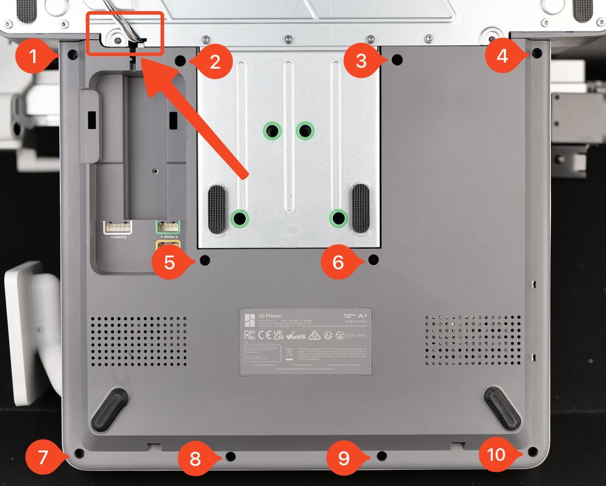
8. Install the wire bracket and connect the wires
In the final step, carefully align the wire bracket then push it downwards while making sure the USB cable is fully pushed against the printer frame.
Then, tighten the screw shown in the image to lock it in place. Avoid overtightening the screw as this is screwed into the plastic frame.

Next, re-connect the Camera, Motor X and Motor Z cables to finish the installation.

This completes the installation process
Verify the functionality
To ensure everything works as expected, turn on the printer and try to heat the bed to 50C
If the heatbed temperature is raising, this confirms the installation was correct.
Calibration step after the operation
No calibration step is required.
Potential problems and solutions
If you encounter problems during the installation of a new AC Board, please check the potential problems and solutions listed below:
The Camera is not working
Confirm the camera wire is fully installed as shown in Passo 8. Install the wire bracket and connect the wires
The X-axis / Z-axis is not working
Confirm the X motor and Z motor wires are fully installed as shown in Passo 8. Install the wire bracket and connect the wires
The screen displays an error message
The USB cable might not be fully inserted. Loosen the screw holding the wire bracket in place, then re-connect the USB cable as shown in Passo 8. Install the wire bracket and connect the wires
The heatbed is not heating
The heatbed might be faulty. Report this issue to Customer Suppoort and wait for their reply to offer a solution.
Notas Finais
We hope this guide has provided clear and practical support.
If the issue remains unresolved, please submit a support ticket and include your recent printer logs and additional pictures or other details. Our customer support team will review your request and provide detailed assistance.
You can also visit Bambu AI, which can instantly answer common questions and provide you with operational guidance.


