
Printer Circuit Failure Troubleshooting – A1
Bambu Lab A1 • Série Bed-Slinger A1
Printer Circuit Failure Troubleshooting – A1
When to Use This Guide
If your device encounters the following issues, refer to this document for troubleshooting.
- The printer power indicator does not light up after connecting the power supply;
- The printer power indicator works normally after connecting the power supply, but the screen does not light up, and the software shows the device is offline;
Important Notes Before Troubleshooting
Before starting formal troubleshooting, you first need to understand the status of the mainboard indicator, toolhead indicator, HMS indicator, and internal power supply indicator.
Normal Status: TH Board Indicator Steady Green
To observe the toolhead indicator, you need to open the toolhead rear cover. Pull the bottom of the rear cover and pry it open carefully.
https://public-cdn.bblmw.com/wiki/video/A1M-TH.mp4
Normal Status: MC Indicator Green Flashes Once Every 5 Seconds
https://public-cdn.bblmw.com/wiki/video/A1-MC.mp4
Normal Status: AP Indicator Green Flashes Once Every 1 Second
https://public-cdn.bblmw.com/wiki/video/A1-AP.mp4
Normal Status: Internal Power Supply Indicator Steady Green
You need to refer to Replace Internal Power Supply first and remove the bottom cover of the printer to observe the internal power supply light.

Aviso de Segurança
Important Notice!
This Guia de Solução de Problemas involves frequent plugging and unplugging of connectors. Before performing any maintenance or connector plugging/unplugging work on the printer and its electronic devices (including the toolhead cable), please turn off the printer power and disconnect the power supply to avoid short circuits caused by live operations, which may lead to additional electronic device damage and safety hazards. After completing the plugging/unplugging, turn on the printer power and observe the status of the indicator. At this time, only observe the status of the indicator, and do not touch the cable plug directly.
When performing maintenance or troubleshooting on the printer, please first confirm the temperature of the hotend and heatbed to avoid operating in a high-temperature state. If you must operate in a high-temperature state, please wear heat-insulating gloves to ensure safe and effective execution of maintenance work.
If you have any questions about this guide, please click here to submit a ticket, and we will reply promptly and provide you with the required assistance.
Required Tools and Materials
- H2.0 allen key
- H1.5 allen key
- PH2 Phillips screwdriver
- Tweezers
- Multimeter (optional)
Power Switch Indicator Off
After the mains power is connected to the device and the switch is pressed, the white indicator of the power switch will light up automatically. If the white indicator of the switch cannot light up, it indicates a fault in the power cord or the power switch.

Passo 1: Power Cord Fault
The printer power cord uses a standard plug. Please use a power cord of the same type for power-on testing. Turn on the printer and observe whether the white indicator lights up. If the indicator returns to normal, it indicates a power cord fault, and a new power cord needs to be replaced.
Passo 2: Fuse Blown or Switch Fault
A 250V 6A fuse is installed inside the switch. You can use tweezers to pry out the fuse mounting base. Since some fuse housings are opaque, the fuse status cannot be observed directly. You can use a multimeter or other methods for testing.
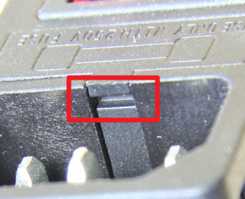
If your phone supports multi-touch, the screen type is “capacitive screen”. You can pinch one end of the fuse with your fingers and touch the other end to the phone screen to observe whether the screen responds to the tap. If it does, the fuse is normal.

Set the multimeter to the beep mode (or resistance mode), and touch the metal caps at both ends of the fuse with the test leads: if there is a beep sound or the resistance value is close to 0 Ω, it indicates the fuse is normal; if there is no beep sound, the display shows “OL” (open circuit) or the resistance value is very large, it indicates the fuse has blown, and a new switch socket needs to be replaced. You can refer to How to Use a Multimeter to Check Circuit Integrity to learn the basic usage of a multimeter.
Power Switch Indicator On
If the power switch indicator lights up normally, the issues of the screen not lighting up and the software showing the device is offline are related to faults or short circuits in the AP (MC) board module, TH board module, or internal power supply.
Troubleshooting Method:
If the indicators of the remaining circuits return to normal after disconnecting a specific connector, it indicates that the module connected to this interface is faulty. If the indicator of a mainboard still does not return to normal after disconnecting all connectors on the mainboard, it indicates the mainboard is faulty.
All AP/MC/TH Indicators Are Off
The input voltage of the printer mainboard is 24V, supplied by the internal power supply. If the output/input of the internal power supply is abnormal, the mainboard will not be powered on, resulting in all indicators not lighting up.
- Refer to Replace Internal Power Supply, loosen the screws #1 and #2 in the figure below to remove the mainboard power supply cable. If the indicator is still abnormal after restarting, you need to replace the internal power supply with a new one.
- If the power indicator returns to normal after removing the mainboard power supply cable, it indicates the internal power supply is not faulty, please continue with subsequent troubleshooting.
 |
 |
All AP/MC/TH Indicators Are Abnormal (Troubleshooting for AP/MC Board Module)
B[First Disconnect the USB-C Plug on the TH Board] –> C[Power On and Observe Indicator Status]
C –> D{Do AP or MC Indicators<br/>Return to Normal?}
D — Yes –> E[Fault Is in the TH Board Module<br/>Perform Further Troubleshooting<br/>on the TH Board Module]
D — No –> G[Fault Is in the AP or MC Board Module]
G –> H[Refer to the Mainboard Replacement Guide<br/>Remove All Module Plugs<br/>and the SD Card from the Mainboard]
H –> I[Power On and Observe Indicators]
I –> J{Do Indicators Return to Normal?}
J — Yes –> K[Install Each Module Plug<br/>and the SD Card One by One]
K –> L{Do Indicators Become Abnormal<br/>After Installing a Certain Module?}
L — Yes –> M[Replace This Module]
L — No –> N[Continue Installing One by One<br/>and Confirm]
J — No –> O[Replace the Mainboard]
classDef proc fill:#dae8fc,stroke:#6c8ebf,color:#000;
classDef decision fill:#fff2cc,stroke:#d6b656,color:#000;
class B,C,E,G,H,I,K,N,O,M,F,L proc;
class D,J,L decision;
If you observe that the AP/MC indicators are abnormal, first disconnect the USB-C plug on the TH board, then power on and observe the indicator status.

-
If the AP (MC) indicators return to normal, the fault is in the TH board module, please perform further troubleshooting on the TH board module.
-
If the AP (MC) indicators remain abnormal, the fault is in the AP (MC) board module. Refer to the Replace Mainboard guide, remove all module plugs and the SD card from the mainboard, then power on and observe whether the indicators return to normal:

- If they return to normal, install each module plug and the SD card one by one. If the indicators become abnormal after installing a certain module, you need to replace this module;
- If they remain abnormal, the mainboard needs to be replaced.

Only the TH Indicator Is Abnormal (Troubleshooting for TH Board Module)
A[TH Board Module Troubleshooting] –> B[First Install the USB-C Plug on the TH Board<br/>Pay Attention to the Direction of the USB-C Cable<br/>and the Small Align Groove on the Back]
B –> D[Disconnect Other Module Connections on the TH Board]
D –> E[Power On and Observe the TH Board Indicator]
E –> F{Does the TH Board Indicator<br/>Return to Normal?}
F — No –> G[Replace with a New TH Board]
F — Yes –> H[Install Each Module Plug One by One<br/>and Confirm After Power On]
H –> I{Does the TH Board Indicator Become Abnormal<br/>After Connecting a Certain Module?}
I — Yes –> J[Replace This Module]
I — No –> K[Continue Installing One by One and Confirm]
classDef proc fill:#dae8fc,stroke:#6c8ebf,color:#000;
classDef decision fill:#fff2cc,stroke:#d6b656,color:#000;
class A,B,C,D,E,G,H,J,K proc;
class F,I decision;
Please first install the USB-C plug on the TH board, paying attention to the direction of the USB-C cable and the small align groove on the back.
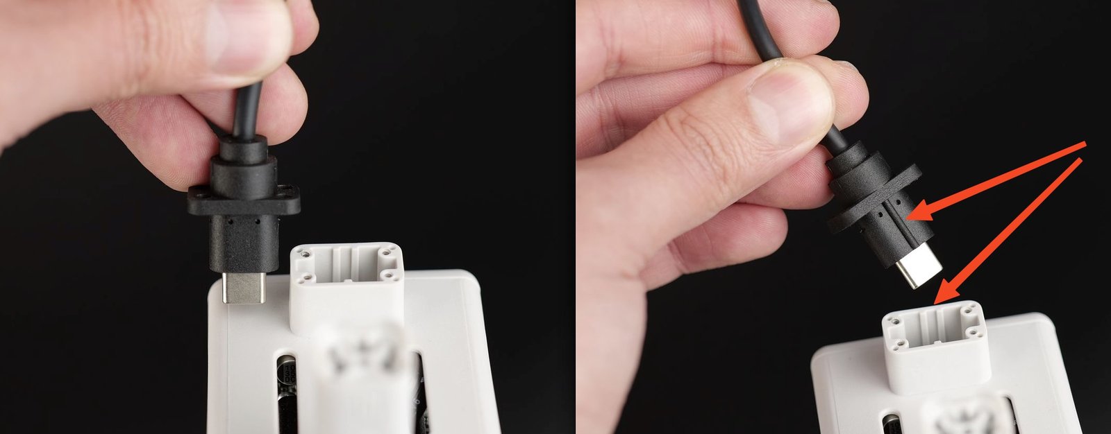
Then, according to Replace with a New TH Board, disconnect other module connections on the TH board, then power on and observe whether the TH board indicator returns to normal.

- If the TH board indicator remains abnormal, you need to replace with a new TH board.
- If the TH board indicator returns to normal, install each module plug one by one and turn on the power to confirm the indicator status. If the TH board indicator becomes abnormal after a certain module is connected to the TH board, you need to replace this module.
Notas Finais
We hope this guide has provided clear and practical support.
If the issue remains unresolved, please submit a support ticket and include your recent printer logs and additional pictures or other details. Our technical team will review your request and provide detailed assistance.
You can also visit Bambu AI, which can instantly answer common questions and provide you with operational guidance.


