
A1 Series First Layer Print Issues – First Layer Too Low, Hotend Moving
Bambu Lab A1 • Série Bed-Slinger A1
A1 Series First Layer Print Issues – First Layer Too Low, Hotend Moving
Applicable Printer Models
A1 series printer
First Layer Too Low
A good first layer is critical for a successful print. If the first layer fails, the entire print is likely to fail.
In this section, we will discuss the reasons behind a too low first layer during printing and provide solutions.
“First layer too low” means that the distance between the nozzle and the build plate is too close, resulting defects such as “peeling,” “bulging,” and “wavy lines” on the first layer.
The images below shows what this issue looks like:
 |
 |
When to Use This Guide
- During first layer printing, issues such as “lifting/peeling,” “wavy patterns,” or raised edges appear;
- Or the nozzle is too close to the build plate — nearly touching or scraping the plate surface — resulting in little to no filament being extruded.
Cause
Heatbed leveling has not been performed
It is crucial to perform heat bed leveling, particularly when changing or replacing the build plate, to ensure accurate leveling for the new print task.
Neglecting this step may result in discrepancies compared to the previous leveling data.
The position of the hotend changed
The position of the hot end changes when printing compared with the bed leveling, and the nozzle is closer to the heat bed resulting in excessive extrusion of the first layer.
Solution
Passo 1. Perform Bed Leveling Before Printing
Running bed leveling before printing is recommended — especially after changing or replacing the PEI build plate.
This helps ensure a consistent and accurate first layer.
To enable this, turn on the Bed Leveling option in the slicer before starting your print.

Passo 2. Check the Hotend and Heater Assembly
If bed leveling has already been performed for the current print and the issue persists, try retightening the hotend heater assembly screws.
-
Check the printer screen and confirm the hotend temperature is below 50°C.
-
Turn off the printer.
-
Remove the front cover.
-
Follow the instructions on the guide sticker to remove the hotend.
 |
 |
-
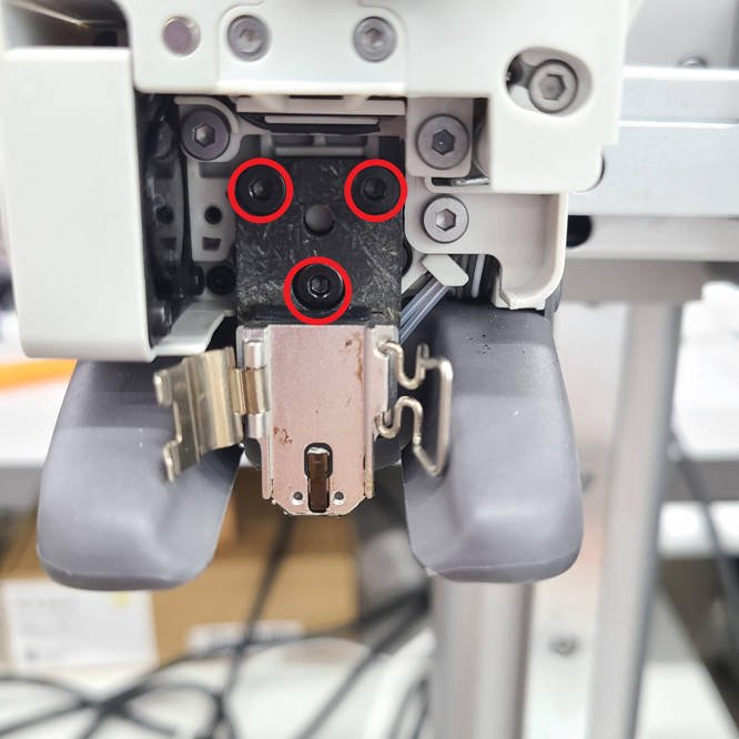
Use an H2.0 hex key to remove the 3 screws that secure the heater assembly.
-
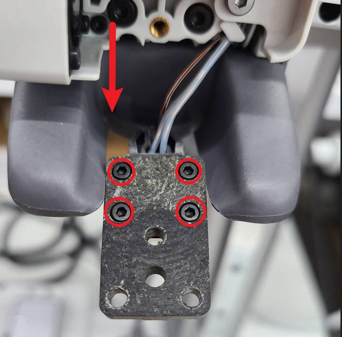
Flip the heater assembly over to access the 4 small screws on the back.
-
Use an H1.5 hex key to retighten these screws as shown below.
⚠️ These screws are small — handle them carefully to avoid stripping or losing them.
 |
 |
Note:
- The 3 heater assembly mounting screws are M3×10.
- The 4 small rear screws are M2×6 (with flat washer and spring washer).
Passo 3. Check the Heater Assembly Buckle
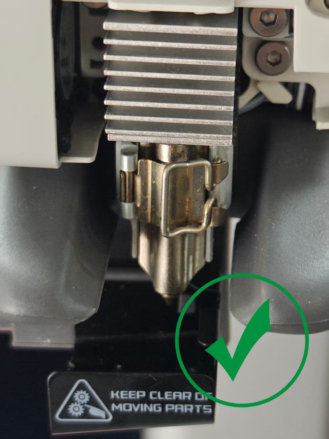
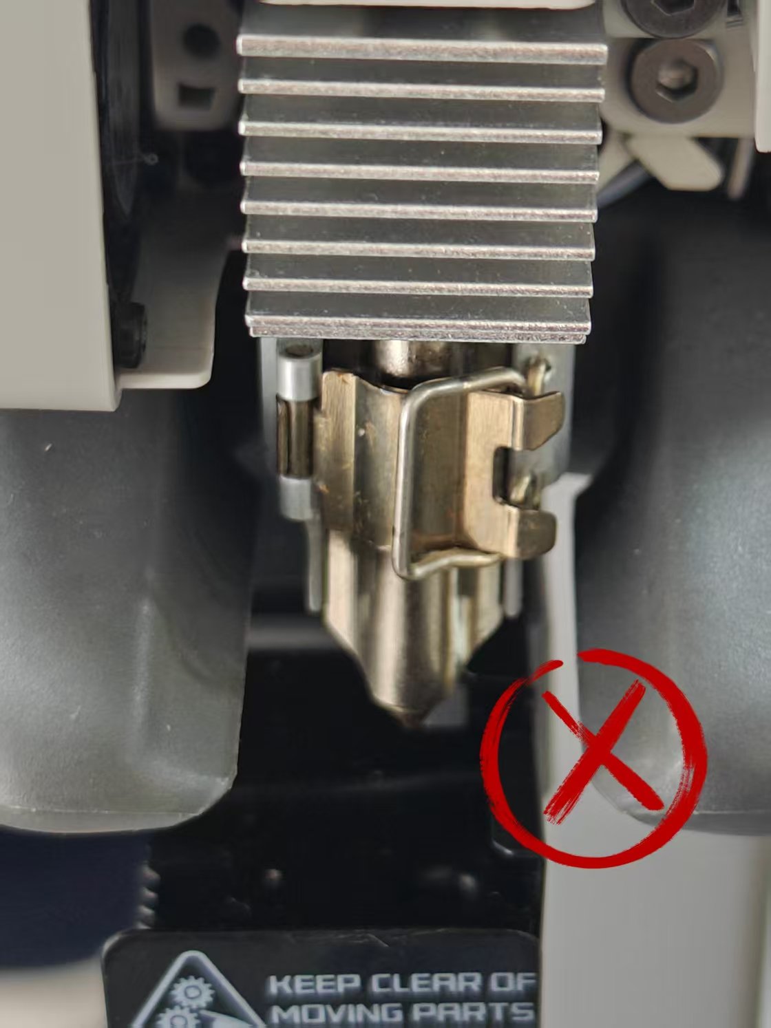
Make sure the heater assembly buckle (clip) is properly fastened. Refer to the images below for the correct orientation.
To verify: Gently try to wiggle the hotend by hand. There should be no obvious movement or looseness.
⚠️ Important: If the heater assembly is not properly secured — or if the clip is damaged — the hotend may shift downward during printing due to extrusion pressure. This can cause the nozzle to compress the first layer too much or even scrape the build plate.

| ✅ Correct — Buckle properly fastened | ❌ Incorrect — Buckle not properly fastened |
 |
 |
After Reassembly:
- Reinstall the hotend and front cover.
- Power on the printer.
- Navigate to the Calibration menu on the printer screen.
- Run Auto Bed Leveling to recalibrate.

Passo 4: Adjust G‑code
Note: This method is only for a quick temporary fix of first‑layer issues and may introduce new local defects elsewhere (e.g., after correcting a low spot, a previously normal area may become too high). After addressing the root cause, it is recommended to restore the default settings and focus on bed leveling.
Suggested Adjustment Ranges:
- Texture board:
-0.02 mm ~ 0 mm - Non‑texture board:
-0.01 mm ~ 0.01 mm
Adjustment Procedure:
- Edit the G‑code command
- Texture board: In Printer Settings → Printer Start G‑code, locate
G29.1and change the original commandG29.1 Z{-0.02}toG29.1 Z{xxx}(replacexxxwith the desired offset). If the first layer is too low, set it toZ{0}, which effectively raises the nozzle by 0.02 mm relative to the default during printing (the toolhead is usually pressed down 0.02 mm on a texture board to ensure a uniform first layer).
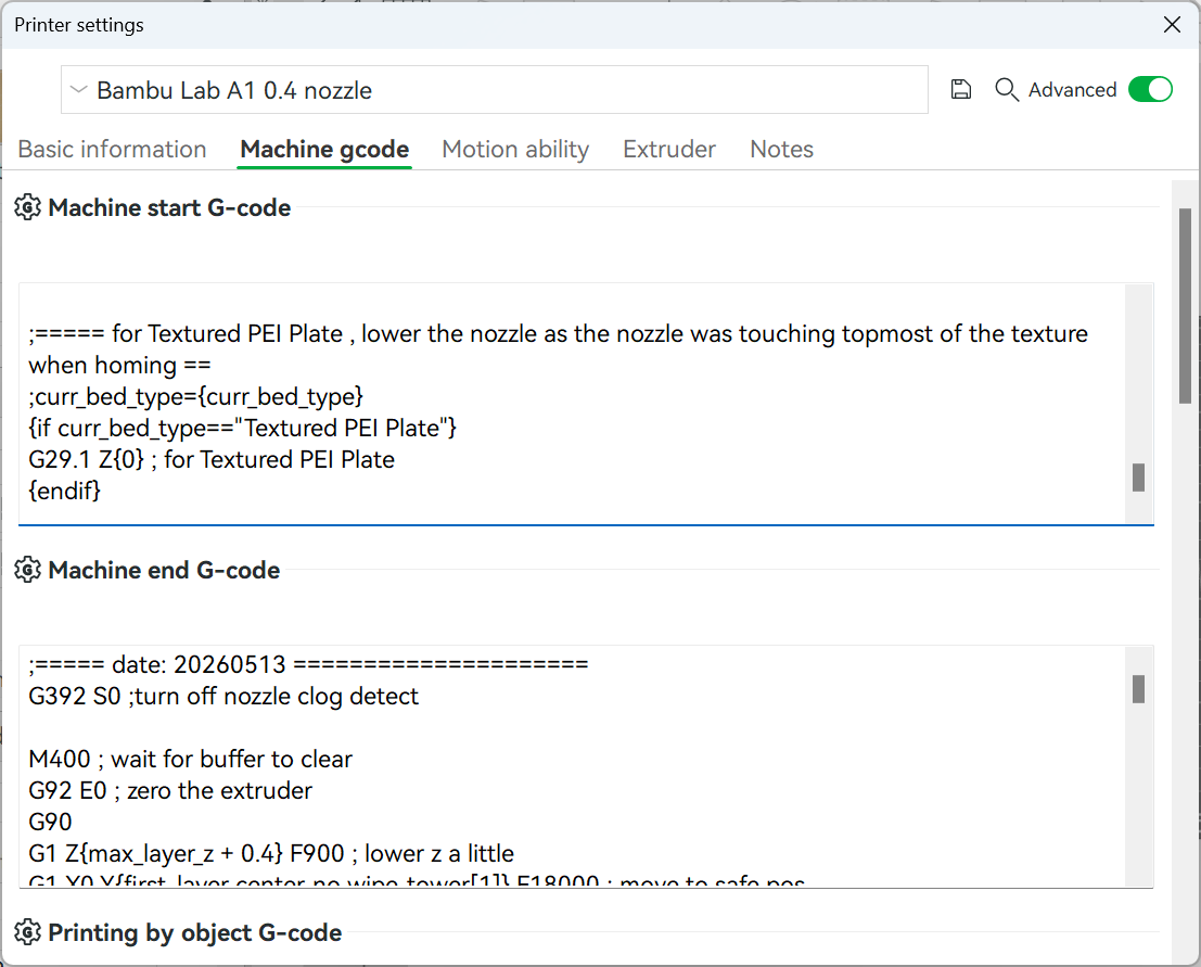
- Non‑texture board (e.g., glossy board): For other board types, you need to add a new command
{else} G29.1 Z{xxx}. Insert this code at the same location as mentioned above, as shown in the image.

-
Adjust the logic
- First layer too high → decrease the offset (e.g., change from
-0.02to-0.03). - First layer too low → increase the offset (e.g., change from
-0.02to-0.01).
- First layer too high → decrease the offset (e.g., change from
Notas Finais
Esperamos que o guia detalhado fornecido tenha sido útil e informativo.
To ensure a safe and effective execution, if you have any concerns or questions about the process described in this article, we recommend submitting a chamado técnico relatando o seu problema. Por favor, inclua uma foto ou vídeo ilustrando o problema ao enviar o chamado técnico.


