
Substituição Cooling Ventilador / Cooler For Hotend e Bico
Bambu Lab H2D • Série Comercial H2
Substituição Cooling Ventilador / Cooler For Hotend e Bico
Note: This page uses the H2D machine as an example. The replacement steps for the H2C are similar.
⚠️ Important Reminder
The eddy sensor coil connectors on the H2D feature this compact connector design. When removing the connector, please hold the base of the connector with your hand and lift straight up, perpendicular to the PCB surface, to unlock it. Never apply force in the horizontal direction to avoid damaging the connector.

Hotend Cooling Fan
The cooling fan for the hotend is installed between the TH board and the extruder to dissipate heat from the hotend, preventing the filament from softening prematurely in the hotend, which could lead to clogging. Below is a list of components included with the cooling fan for the hotend:
-
M2.5×8 screws – for fixing the cooling fan for hotend (x2)
-
BT2.6×8 screws – for fixing the cooling fan for hotend (x2)

Tools and materials needed
-
H2.0 Allen key
-
H1.5 Allen key
⚠️ Aviso de Segurança
It’s crucial to power off the printer before conducting any maintenance work, including work on the printer’s electronics and toolhead wires. Performing tasks with the printer on can result in a short circuit, leading to electronic damage and safety hazards.
During maintenance or troubleshooting, you may need to disassemble parts, including the hotend. This exposes wires and electrical components that could short circuit if they contact each other, other metal, or electronic components while the printer is still on. This can result in damage to the printer’s electronics and additional issues.
Therefore, it’s crucial to turn off the printer and disconnect it from the power source before conducting any maintenance. This prevents short circuits or damage to the printer’s electronics, ensuring safe and effective maintenance. For any concerns or questions about following this guide, open a new ticket in our Support Page and we will do our best to respond promptly and provide the assistance you need.
Remove the Hotend Cooling Fan
This page provides step-by-step guidance on which components need to be disassembled to replace the Hotend Cooling Fan.
Do not disassemble any components other than those specified in this section.
Passo 1: Remove the part cooling fan duct
Firstly use a H2.0 hex key to remove the four fixed screws (BT3x8), shown in the image below.
 |
 |

Then hold the rear end of the part cooling fan duct and pull it downwards to remove the duct carefully.
 |
 |
Passo 2: Remove the part cooling fan
Use a H2.0 hex key to remove the two fixed screws, BT3x20 marked with a square symbol.
Do not remove the part cooling fan yet. There are still two screws underneath. These screws are marked with a red arrow, and will be removed next.

Using the same H2.0 hex key, remove the remaining two BT2.6×8 screws now marked with a circle symbol.
 |
 |
Carefully pull the part cooling fan assembly away from the toolhead.

Tear off the acetate tape on the plug, then unplug it. Leave the removed tape on the circuit board for easier installation later on.
ℹ️ Please note that this type of plug should be carefully pushed upward along the plane where the plug is located, rather than pulled out along the direction of the cable.
 |
 |
Passo 3: Remove the Extruder connection board
Disconnect the following connectors on the interface board in sequence:
| No. | Connected to | No. | Connected to |
|---|---|---|---|
| 1 | 2004 switching motor | 2 | TH board |
| 3 | Left hotend heating assembly | 4 | 2004 lifting motor |
Note: The 2004 switching motor cable (No. 1), FPC cable (No. 2) and 2004 lifting motor cable (No. 4) are secured by latches. Unlock the latches before pulling out the FPC cables.

No. 1. 2004 switching motor. Carefully open the latch before removing the FPC cable.
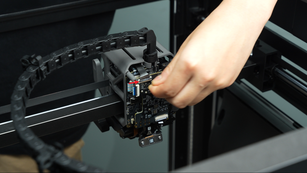
No. 2. TH board. Carefully open the latch before removing the FPC cable.

No. 4. 2004 lifting motor. Carefully open the latch before removing the FPC cable.

No. 3. Left hotend heating assembly.
When peeling off the foam on the left hotend heating assembly connector (No. 3), it is recommended to loosen the connector first, then peel from bottom to top to maintain the foam’s integrity, as the images below show:
 |
 |
Proceed to remove the board.
Use an H1.5 Allen key to remove the 2 fixing screws (M1.6×4).

Gently wiggle the extruder connection board near the 2004 switching motor connector and carefully remove it.

Disconnect the 2004 switching motor FPC plug (#1), the TH board interface FPC plug (#2), and the 2004 lifting motor FPC plug (#3) from the interface board in sequence.

| Serial Number | Connection object |
|---|---|
| 1 | 2004 Motor Switching |
| 2 | TH board cabling |
| 3 | Power cord of induction heating assembly |
| 4 | 2004 Lifting Motor |
Note: The plugs are secured with clips. Unlock the clips before unplugging the FPC cable.
- Position 1:

- Position 2:

- Position 3:

After unplugging these connectors one by one, use a 1.5 mm hex wrench to remove the two screws and release the heating element power cable.
 |
 |
Remove the two extrusion interface board fixing screws (M1.6 × 4).
 |
 |
Gently shake the extrusion interface plate near the 2004 motor plug switch, then carefully remove the extrusion interface board.

Passo 4: Disconnect the cables on the TH Board
Disconnect all connectors on the TH board in sequence. Refer to the images and tables for the specific cable connectors and their connections.
| No. | Connected to | No. | Connected to |
|---|---|---|---|
| 1 | Extruder connection board – TH board FPC cable | 7 | Right eddy current coil |
| 2 | 3513 extruder servo motor | 8 | Nozzle camera |
| 3 | Toolhead sensor FPC cable | 9 | Toolhead camera |
| 4 | Left hotend heating assembly – Already removed | 10 | Cooling fan for hotend |
| 5 | Left eddy current coil | 11 | Right hotend heating assembly |
| 6 | Lifting hall effect sensor |

There are three types of plugs on the TH board, and you must use different methods to disconnect depending on the type of plug.
-
Connectors 1, 2, 3, 6, 8, and 9 are secured by latches. Unlock the latch to remove the cable.
-
Connectors 5, 7, and 10 are secured from the front. Pull it vertically upward relative to the TH board to disconnect the connection.

- Connectors 4 and 11 are secured by headers. Pull directly to disconnect.
The detailed steps to disconnect the connection wires on the TH board are as follows:
Detailed steps:
No. 11- Right hotend heating assembly, No. 10- Cooling fan for hotend and No. 3- Toolhead sensor FPC cable
- No. 3 and 11 – Disconnect the right hotend heating assembly cable. Unlock the latch on the toolhead sensor FPC cable and remove the cable.
- No.10 – Firmly hold the plug housing, then pull it vertically upward relative to the TH board to disconnect the connection.
 |
 |
No. 9- Toolhead camera and 8- Nozzle camera
Use tweezers to peel off the backing tape of the toolhead camera and nozzle camera FPC cables. Unlock the latch and remove the FPC cables.
 |
 |
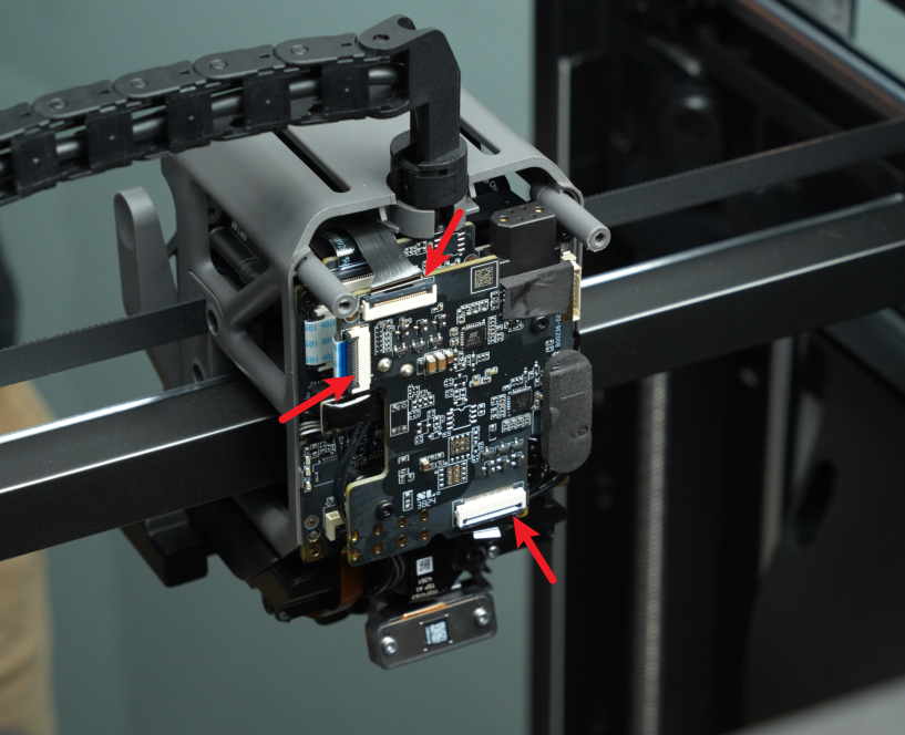
As shown in the figure, there are two cable channels pointed by the red arrows.
The large cable channel at the lower arrow is used to store the cables of the left hotend heating component, and the small cable channel at the upper arrow is used to organize the cables of the left eddy current coil plug, the right eddy current coil plug and the lifting hall plug.
Before unplugging these three small plugs, you need to pull out the cables in the two cable channels in turn to increase the cable length and facilitate unplugging.
Remove the cables from the two cable channels:

No. 5- Left eddy current coil
Firmly hold the plug housing, then pull it vertically upward relative to the TH board to disconnect the connection.

No. 6- Lifting hall effect sensor
Unlock the latch to remove the cable.

No. 7- Right eddy current coil
Firmly hold the plug housing, then pull it vertically upward relative to the TH board to disconnect the connection.

No. 1- Extruder connection board – TH board FPC cable and 2- 3513 extruder servo motor
Unlock the FPC interface and 3513 extruder servo motor interface latches. Remove the FPC cable and place it on the table (keep it safe for later installation). Take out the 3513 extruder servo motor cable from the latch.
 |
 |
Disconnect the plugs on the TH board one by one. The specific cable connectors and their connections are shown below:

| Serial Number | Connection object | Serial Number | Connection object |
|---|---|---|---|
| 1 | 3513 Extrusion Motor | 7 | Right eddy current sensor |
| 2 | Extruded interface board – TH board FPC cable | 8 | Lifting Hall Plate |
| 3 | Hotend fan | 9 | Left eddy current sensor |
| 4 | Induction heating assembly | 10 | Left hotend heating component |
| 5 | Toolhead camera | 11 | Hall effect adapter board for extruders |
| 6 | Nozzle camera |
There are three types of plugs on the TH board, and you can use different methods to disconnect them depending on the type of plug.
ℹ️Note: How to correctly remove the connectors
- The plugs 1, 2 ,4 ,5 ,6 ,8 and 11 are all secured with clips. You need to first open the clips on the connector and then remove the cable.
(The animation below is for the H2D, but the connector is the same)
- In 3, 7, and 9, Pull the connector diagonally down and away from the board. Be carefull, excessive force on the cable might lead to damage to the connector.
(The animation below is for the H2D, but the connector is the same)
- In 10, it is fixed by a power strip, so you can pull it out directly.


Passo 5: Remove the TH Board
First, disconnect the side of the cable chain connected to the rotating base.

Partially pull out the USB-C cable and MC-TH cable from the cable chain, revealing around 10cm of the cables.
 |
 |
Remove two BT2.6×8 screws with an H2.0 Allen key.

Pull the TH board away from the toolhead, revealing the hotend cooling fan.
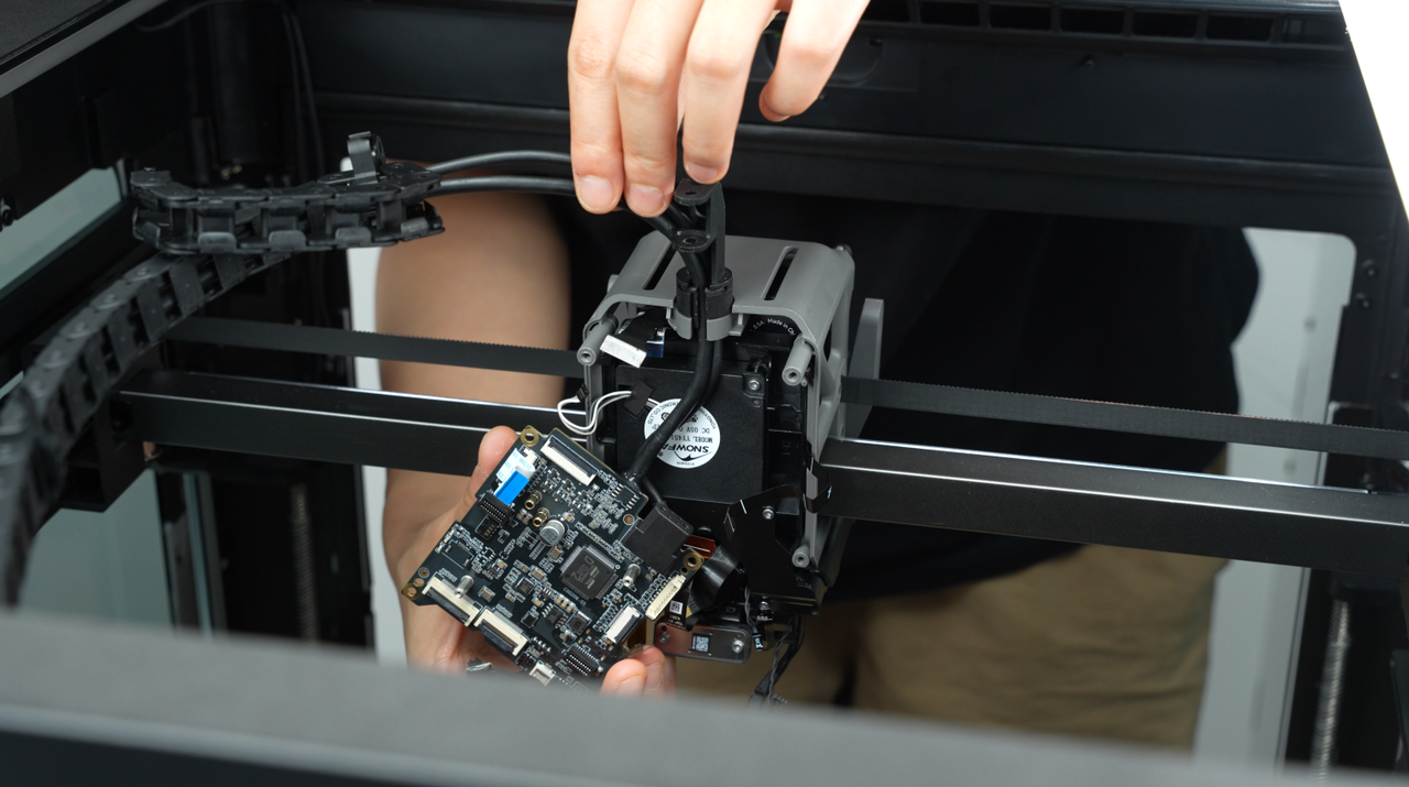
Carefully remove the cables from the cable chain slot.
This allows you to pull the TH to the side.

Passo 6: Remove the Cooling Fan for Hotend
After confirming that the nozzle camera FPC is not stuck to the lifting motor rear cover, use tweezers to pry open the lifting motor rear cover.
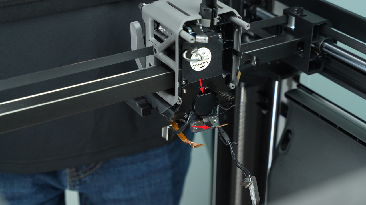 |
 |
- Use an H2.0 Allen key to remove the two fixing screws (M2.5×8).
- These screws are located inside the plastic middle frame slot.
- Insert the screwdriver in the direction shown in the image to unscrew them.
TIP: It is highly recommended to use a screwdriver with a magnetic tip.
 |
 |
⚠️ Check the cable routing slot to ensure no cables are stuck.
Then, pinch the lower part of the cooling fan for hotend and push it out backward.
 |
 |
Install the Cooling Fan for Hotend
Passo 1: Install the Cooling Fan for Hotend
Organize the cables:
- Thread the lifting motor FPC through the hole in the fan bracket, and ensure all other cables are pulled away and not pinched.
Important: It is strongly recommended to confirm that no cables are pinched after installing the cooling fan for hotend before tightening the screws.
From top to bottom and left to right, the cables to be checked include: switching motor, extruder motor, extruder hall sensor board FPC, toolhead camera, nozzle camera, left and right eddy current coils, lifting hall, and lifting motor FPC (the last one should be threaded through the hole behind the motor rotor).
 |
 |
Use an H2.0 Allen key to tighten the two fixing screws (M2.5×8) securing the hotend fan in place.
 |
 |
Snap the lifting motor cover back into place.

Passo 2: Install the TH board
Insert the MC-TH cable and USB-C cable into the cable chain base and toolhead middle housing.
- Snap the thinner cable (USB-C cable) in first, then the thicker cable (MC-TH cable).
 |
 |
Reconnect the cable chain to the cable chain base.
 |
 |
Align the TH board with the screw holes on the toolhead and secure it using two BT2.6×8 screws with an H2.0 hex key.
⚠️ Before tightening the screws, ensure no cables are trapped under the TH board!
Check the following cables:
From top to bottom and from left to right, the cables that need to be checked in turn include: 2004 switching motor, 3513 extruder servo motor, cooling fan for hotend, extruder connection board plug, toolhead sensor FPC cable, toolhead camera, nozzle camera, left and right eddy current coils, lifting hall and 2004 lifting motor cable, left and right hotend heating assemblies.
Passo 3: Reconnect all cables to the TH board
Reconnect all cables to the TH board in sequence. Refer to the images and tables for the specific cable connectors and their connection methods.

| No. | Connected to | No. | Connected to |
|---|---|---|---|
| 1 | Extruder connection board – TH board FPC cable | 7 | Right eddy current coil |
| 2 | 3513 extruder servo motor | 8 | Nozzle camera |
| 3 | Toolhead sensor FPC cable | 9 | Toolhead camera |
| 4 | Left hotend heating assembly | 10 | Cooling fan for hotend |
| 5 | Left eddy current coil | 11 | Right hotend heating assembly |
| 6 | Lifting hall effect sensor |
- Connectors 1, 2, 3, 6, 8, and 9 are secured by latches. Firstly insert the cable and then close the latch.
1 – FPC cable

2 – 3513 extruder servo motor

3 – Toolhead sensor FPC cable

6 – Lifting hall effect sensor

8 – Nozzle camera

9 – Toolhead camera

Tip:
Reattach the toolhead camera and nozzle camera FPC cables. Use tweezers to secure the cables back onto the toolhead.


- Connectors 5, 7, and 10 are secured from the front. Ensure the metal side of the connector faces upward, align the connector with the interface, and press downward to disconnect.
10 – Cooling fan for hotend

5 – Left eddy current coil
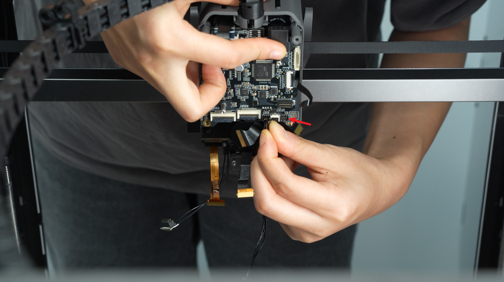
7 – Right eddy current coil

- Connectors 4 and 11 are secured by headers. Align the header with the connector and insert it directly, ensuring it is fully seated.
Insert the cables into the cable slot:
- As shown in the figure, there are 2 cable channels at the arrows.
- The large cable channel at the lower arrow is used to store the left hotend heating assembly cable, and the small cable channel at the upper arrow is used to organize the left eddy current coil plug, right eddy current coil plug and lifting hall plug cables.
- You can reconnect these 3 plugs to the TH board and then re-insert the cables into the small cable channel.

Connect the cables back to the TH board in sequence. There are three types of plugs on the TH board, and each requires a different connection method depending on its type.
in:
- The plugs numbered 1, 2, 4, 5, 6, 8, 9, and 11 are secured with clips. Insert the ribbon cable into the corresponding interface on the TH board, make sure it is fully inserted, and then lock the clips
| Serial Number | Connection object | Serial Number | Connection object |
|---|---|---|---|
| 1 | 3513 Extrusion Motor | 7 | Right eddy current sensor |
| 2 | Extruded interface board – TH board FPC cable | 8 | Lifting Hall Plate |
| 3 | Hotend fan | 9 | Left eddy current sensor |
| 4 | Induction heating assembly | 10 | Left hotend heating component |
| 5 | Toolhead camera | 11 | Hall effect adapter board for extruders |
| 6 | Nozzle camera |
Clip the cable into the cable management clip:
As shown by the arrows, there are two cable management slots. The larger slot (indicated by the lower arrow) is used to hold the cables for the left hotend heating component, while the smaller slot (indicated by the upper arrow) is used to organize the cables for the left eddy current sensor connector, right eddy current sensor connector, and the Hall effect sensor connector. Reconnect these three connectors to the TH board, then insert the cables back into the smaller cable management slot.
The order for inserting the cables is as follows:

Passo 4: Install the extruder connection board
Align the extruder connection board latches with the slots on the TH board.

Install the extruder connection board and tighten the 2 fixing screws (M1.6×4) using an H1.5 Allen Key.

Reconnect the following cables to the extruder connection board:
The name of the cable that corresponds to the number in the picture:
| No. | Connected to | No. | Connected to |
|---|---|---|---|
| 1 | FPC cable | 2 | 2004 switching motor cable |
| 3 | Part cooling fan cable | 4 | Left hotend heating assembly cable |
| 5 | 2004 lifting motor cable |

Connect the left hotend heating assembly to the TH board. Insert the header into the TH board’s socket and secure the foam onto the extruder connection board.

For No. 1, 2, and 5, these plugs are fixed by buckles. You need to insert the cable into the interface of the extruder connection board, and then tighten the buckle after the cable is fully inserted;
- Align the pins on the extrusion interface board with the slots on the TH board, and install the extrusion interface board onto the TH board.

- Tighten the two retaining screws (M1.6×4) using an H1.5 hex wrench.

- Reconnect the cables to the extrusion interface board in sequence.
| Serial Number | Connection object |
|---|---|
| 1 | 2004 Motor Switching |
| 2 | TH board cabling |
| 3 | Power cord of induction heating assembly |
| 4 | 2004 Lifting Motor |
Passo 5: Install the part cooling fan
With the metal side facing up, align the interface, then press down the part cooling fan plug and stick back the acetate tape.
 |
 |
Align the screw holes, with the ones on the part cooling fan, and tighten the 4 fixing screws.(BT3x20 marked with a square symbol, BT2.6×8 marked with a circle symbol)

 |
 |
Passo 6: Install the part cooling fan duct
The left hotend heating assembly cable needs to be installed in the cable management slot.
- Before installing the duct, make sure to press the hotend heating assembly cable into the cable management slot to prevent the duct from pressing on the cable.
 |
 |
First, install the front 1/4 of the duct to make it easier to tilt the rear half of the duct, avoiding interference with the nozzle camera.
Then, grasp the rear half of the duct and push it upwards.
 |
 |
After pushing it in, gently bend the sides of the duct outward, slotting them onto the tool head on each side, and then firmly press the duct upwards to secure it in place.


Next, push the top of the front section of the duct forward to ensure a snug, gap-free fit.

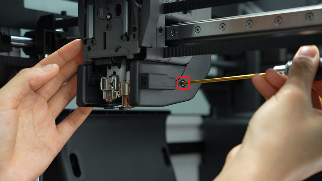
Use an H2.0 hex key to tighten the four fixing screws (BT3x8).


Verify the Functionality
Connect the power, turn on the printer.
Navigate to the Controls (1) menu and click the **Nozzle & Extruder **(2) option.

Select the Left or Right nozzle (3) and click on the **temperature **to input a value (4).

Lastly, increase the hotend temperature to 100 °C

✅ Use a piece of paper in the middle of the two hotends, if it moves as the hotend temperature reached the 100 °C, then the fan is working.

❌ If the paper does not move and no airflow is felt, further inspection is required.
- First, check that the Hotend temperature is correct.
- Next, make sure all plastic parts and air ducts on the Toolhead are installed correctly.
- Finally, check that all connectors are fully seated and properly connected.
Notas Finais
Esperamos que o guia detalhado fornecido tenha sido útil e informativo.
If this guide does not solve your problem, please submit a chamado técnico, we will answer your questions and provide assistance.
If you have any suggestions or feedback on this Wiki, please leave a message in the comment area. Thank you for your support and attention!


