
H2D Toolhead Scraping the Build Surface – Troubleshooting Manual
Bambu Lab H2D • Série Comercial H2
H2D Toolhead Scraping the Build Surface – Troubleshooting Manual
Issue Description
When starting a print or calibration, components on the toolhead may scrape against the build plate, resulting in surface damage. This issue may be caused by several factors. Please refer to the troubleshooting steps below to help identify and resolve the root cause.
Note: Please remember to document the incident with clear photos, which will assist the technical support team in diagnosing the issue more effectively. If possible, insert a USB flash drive into the printer during the print and enable video recording. Reviewing the footage can significantly speed up the troubleshooting process. Click here to learn how to enable the video recording function.
Possible Causes
We recommend checking each of the following items in the order listed.
1. Improper Installation of the Hotend Retaining Clip
If the retaining clip is not securely fastened during hotend installation, the hotend may not be properly fixed in place. As the extruder pushes filament through, the hotend can be gradually forced downward. This shift may result in an incorrect nozzle-to-bed distance, eventually causing the nozzle to scrape the build surface.

How to Identify This Issue
- The scrape marks on the build surface closely follow the nozzle’s movement path.

- Remove the silicone sock and inspect whether the retaining clip is properly secured in place.

Example of an improperly secured hotend retaining clip |

Example of a properly secured hotend retaining clip |
Solution
Re-secure the hotend properly by following the steps shown in the animation below.

2. Deformed or Damaged Flow Blocker
During printing or calibration, the flow blocker may become severely deformed due to other reasons. The flow blocker might sit lower than the hotend, causing it to scrape the build surface when the hotend moves close to the print bed.
Below is an example of a deformed flow blocker:

How to Identify
-
Check if the flow blocker is severely deformed, causing it to sit lower than the bottom of the hotend;
-
Notice many fine, irregular scratches on the build surface.
In the image below, the flow blocker is deformed, and the hotend clip on the left side is also incorrectly installed:

Solution
Please refer to this link to replace the flow blocker.
3. Uneven Build Plate
Although the build plate is leveled at the factory, some units may experience significant tilting during shipping due to bumps or impacts. This usually does not affect overall functionality, and can be resolved by performing manual bed leveling following this H2D Manual Bed Leveling Guide.
How to Identify
Typically, when the build plate is uneven, it tends to tilt around the X-axis. This causes the side near the printer’s door to be higher than the center of the build plate. During automatic leveling (at the lower-left corner of the bed) and while printing the pre-extrusion line (at the lower-right corner), the nozzle may scrape the build plate.

Solutions
-
Perform manual bed leveling by following the Wiki guide.
-
Future firmware updates will include safeguards to prevent damage to the build plate even if manual leveling is not performed.
4. Loose Heating Assembly Components
If the screws securing the heating assembly (including the heating block and ceramic base) are not tightened properly, gaps may form. When the extruder starts feeding filament, the molten material could push the entire heating assembly downward. This results in the nozzle being too close to the build plate, causing it to scrape the surface.
How to Identify
-
Scrape marks generally match the nozzle’s movement path.
-
Remove the silicone sock to confirm that the nozzle clamp is properly secured.
-
Remove the toolhead to check whether the screws fixing the heating assembly are loose.
3.1 Tighten the Front and Rear Screws of the Ceramic Base:
-
First, loosen the screws securing the ceramic base (4 screws on the left side and 3 screws on the right side).
-
If you need to remove the heating assembly on the left side, please also remove the two screws on the left-side cable management bracket. Refer to the image below for the exact locations.
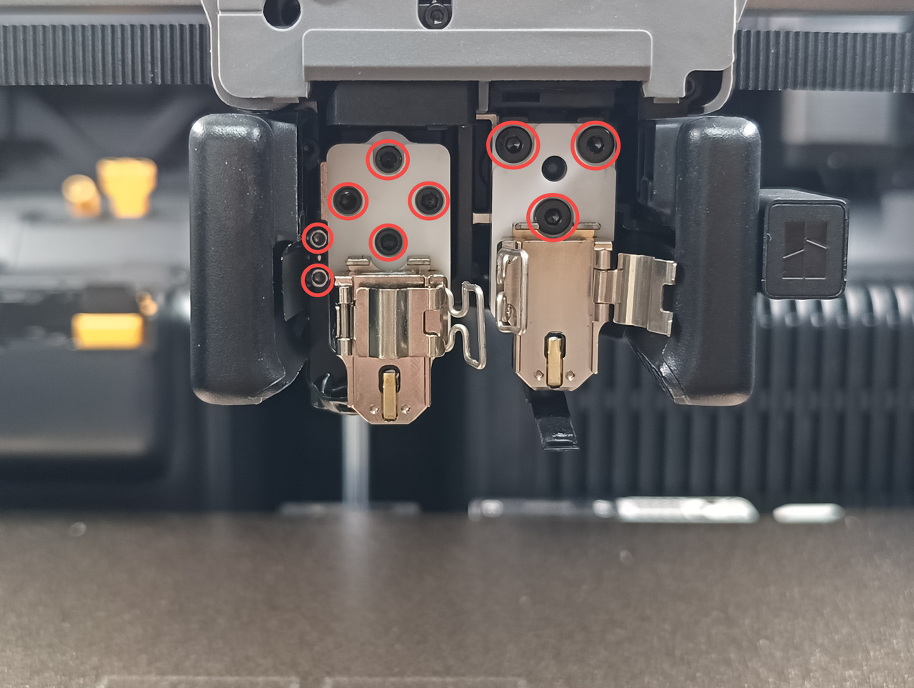
- Then, moderately tighten the 4 screws at the back of the heating assembly by about one-eighth of a turn.
Note: If the screws are already tight, do not forcefully overtighten them to avoid damaging the ceramic base.


- Reinstall the left and right ceramic bases and securely tighten the fixing screws.
3.2 Check Nozzle Installation:
-
When installing, press the nozzle downward before fastening the clamp. Make sure the clamp is properly secured to prevent any looseness.
-
After installation, manually shake the nozzle to check its firmness. If there is noticeable movement, it indicates the toolhead is not fully secured. As shown in the animation below, if the nozzle moves when shaken, it means the installation is incorrect.

Notas Finais
Esperamos que o guia detalhado fornecido tenha sido útil e informativo.
If this guide does not solve your problem, please submit a chamado técnico, we will answer your questions and provide assistance.
If you have any suggestions or feedback on this Wiki, please leave a message in the comment area. Thank you for your support and attention!


