
H2S Laser Upgrade Guide
Bambu Lab H2S • Série Comercial H2
H2S Laser Upgrade Guide
H2S Laser Upgrade
To upgrade your H2S to the H2SL version, simply purchase the 10W Laser Upgrade Kit and strictly follow the steps outlined in this guide.
The installation process for the laser upgrade is relatively complex. Before operation, please carefully read this guide and watch the instructional video for the laser upgrade kit to ensure you have fully mastered the installation method.
Note: Some diagrams in this guide use illustrations from the H2D model; however, the core installation logic is consistent with that of the H2S, so the upgrade and replacement process will not be affected.
Required Tools and Materials
- Laser Upgrade Kit
- H2.0 Allen Key
- Estimated Time: 1 hour
Aviso de Segurança
IMPORTANT!
It’s crucial to power off the printer before conducting any maintenance work, including work on the printer’s electronics and tool head wires. Performing tasks with the printer on can result in a short circuit, leading to electronic damage and safety hazards.
During maintenance or troubleshooting, you may need to disassemble parts, including the hotend. This exposes wires and electrical components that could short circuit if they contact each other, other metal, or electronic components while the printer is still on. This can result in damage to the printer’s electronics and additional issues.
Therefore, it’s crucial to turn off the printer and disconnect it from the power source before conducting any maintenance. This prevents short circuits or damage to the printer’s electronics, ensuring safe and effective maintenance. For any concerns or questions about following this guide, we recommend submitting a chamado técnico relatando o seu problema. and we will do our best to respond promptly and provide the assistance you need.
Video Guide
The following reference video is an operational demonstration of the H2D laser upgrade. Except for the need to skip the “Side Glass Replacement” step, the rest of the upgrade process is identical to that of the H2S model and can be directly followed.
Operation Guide
Unpack the Laser Upgrade Kit
- Carefully cut open the Laser Upgrade Kit Box.

- Remove foam inserts to reveal the kit components.

- Remove all kit components from the foam and place them on your working surface.
Note: The BirdsEye camera clips and screws are not marked in the following image, but are included in the upgrade kit.
- Laser Base
- Top Laser Protection Plate
- Front Laser Safety Window
- Slats *6
- Birds Eye Camera
- Allen Key H2.5
- Smoke Ventilation pipe
- Air Assist Tube
- Air Pump Connection Cable
- 10W Laser Module
- Pipe Clamp
- Emergency Stop Button
- Cleaning Brush
- Air Pump
- Smoke Ventilation Pipe Adapter
- Pressing Block *4

Replace the Front Laser Safety Window
Remove the normal H2D Front Glass Door
- Remove two screws on the top and bottom of the door near the hinge.
Note: While removing the last screws, be sure to hold the front glass door with your hands to prevent it from falling and getting damaged.


- Remove the front door glass.
Note: Take special care to avoid anything hard from bumping into the glass door while handling it or storing it. Take special care to protect the outer edges of the glass.

Install the Front Laser Safety Window
- Remove the protective film from the front laser safety window;

- Gather the 4 screws which held on the original door.

- Hold the laser safety window in place and aligned with the screw holes with your hand and tighten the two screws on the top and two on the bottom. The screws should be snug, but do not overtighten.


- After installation is complete, test the front laser safety window by opening and closing it to check that it is properly installed.

Install the Birdseye Camera
Tip: The camera is designed for printer functions only. Please ensure the camera is correctly installed so that the camera field of view is correctly pointing towards the print area, to avoid any detection issues of the build plate or nozzles.
Fix the Birdseye Camera
- Remove the screw from the AP board cover, as shown in the picture.

- Open the AP board cover by pulling from the bottom.

- Use an Allen key to gently push the LED cable out of the way as pictured to avoid pinching the cable when installing the birdseye camera.

- Install the birdseye camera. Align the two side buckles on the camera housing with the two small grooves on the printer as shown.


- Gently press the camera housing upward until you hear a “click” sound, indicating it is securely installed.

- Wipe the camera lens with a microfiber cloth to remove any dust.

Connect the BirdsEye Camera Cable
- Remove the adhesive backing of the cable.

- When routing the cable, avoid blocking the chamber temperature sensor and the flame sensor which are highlighted in the image below.

Note: Apply continuous and firm pressure for about 30 seconds during attachment to ensure proper adhesion.

- Carefully open the thin latch in the top left corner of the AP board.

- Route the camera cable behind the other wires and connect it to the AP board to the connector with the latch just opened.
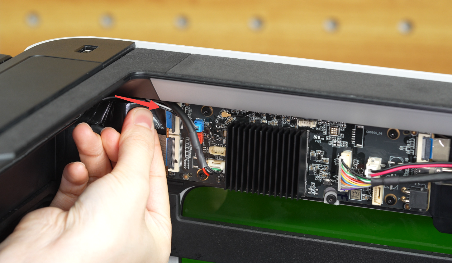
- Ensure the cable is fully seated and straight and press the latch firmly to lock it.

- Close the AP board cover.

- Tighten the fixed screw.

- Peel off the sticker backing from the cable buckle.

- Align the buckle with the screw hole to the right of the BirdsEye camera and stick it in place as shown below.


Note: Apply continuous and firm pressure for about 15 seconds during attachment to ensure secure adhesion.

- Install the second buckle in the middle section between the BirdsEye camera and the first buckle, then press it firmly into place;

- Tighten the screw to secure the buckle.
Note: There are no reserved screw holes on some versions of the printer. You only need to glue the two clips as required.

Install the Air Pump
Pay attention to the difference in length of the air assist tubes. Note the sticker on the long tube.
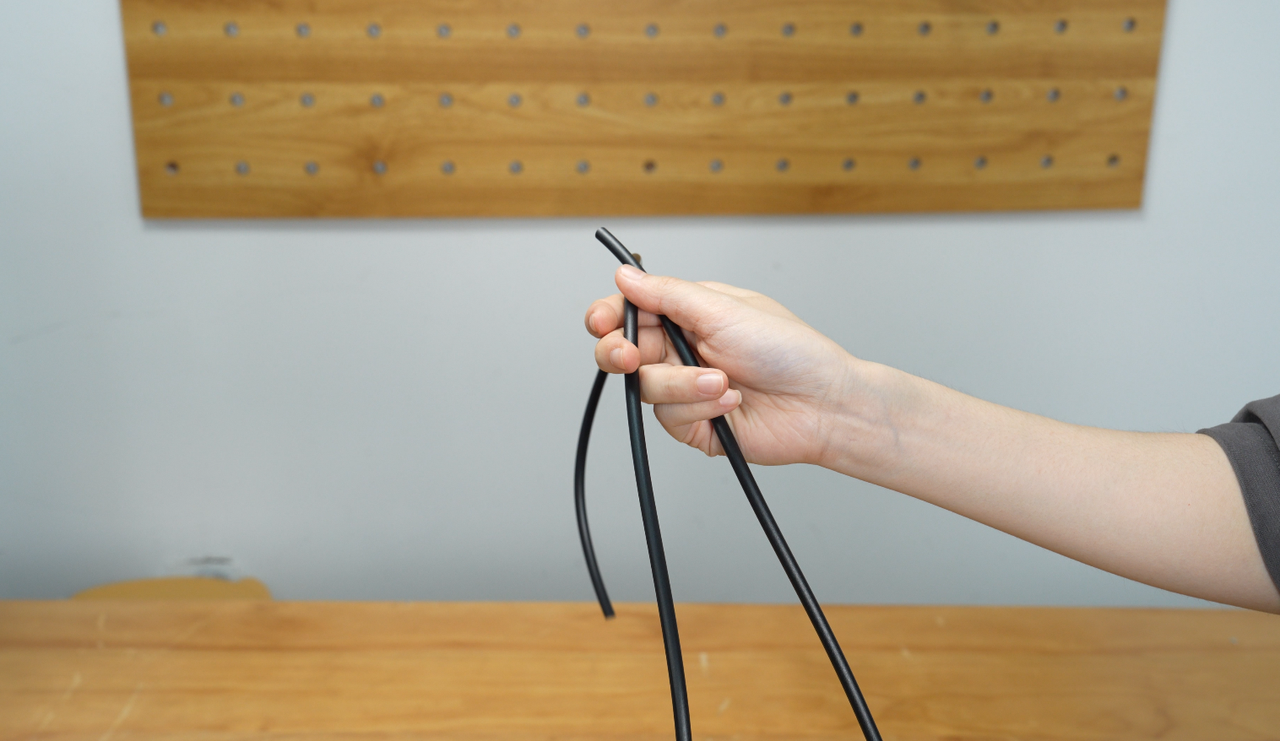

- Insert the short air assist tube into the TPU filament inlet at the back of the printer.

- Secure the air assist tube in the two clips along the toolhead cable chain.

- Plug the air pump cable into the air pump.

- Plug the 4-pin connector of the air pump cable into one of the 4-pin ports on the back of the printer.
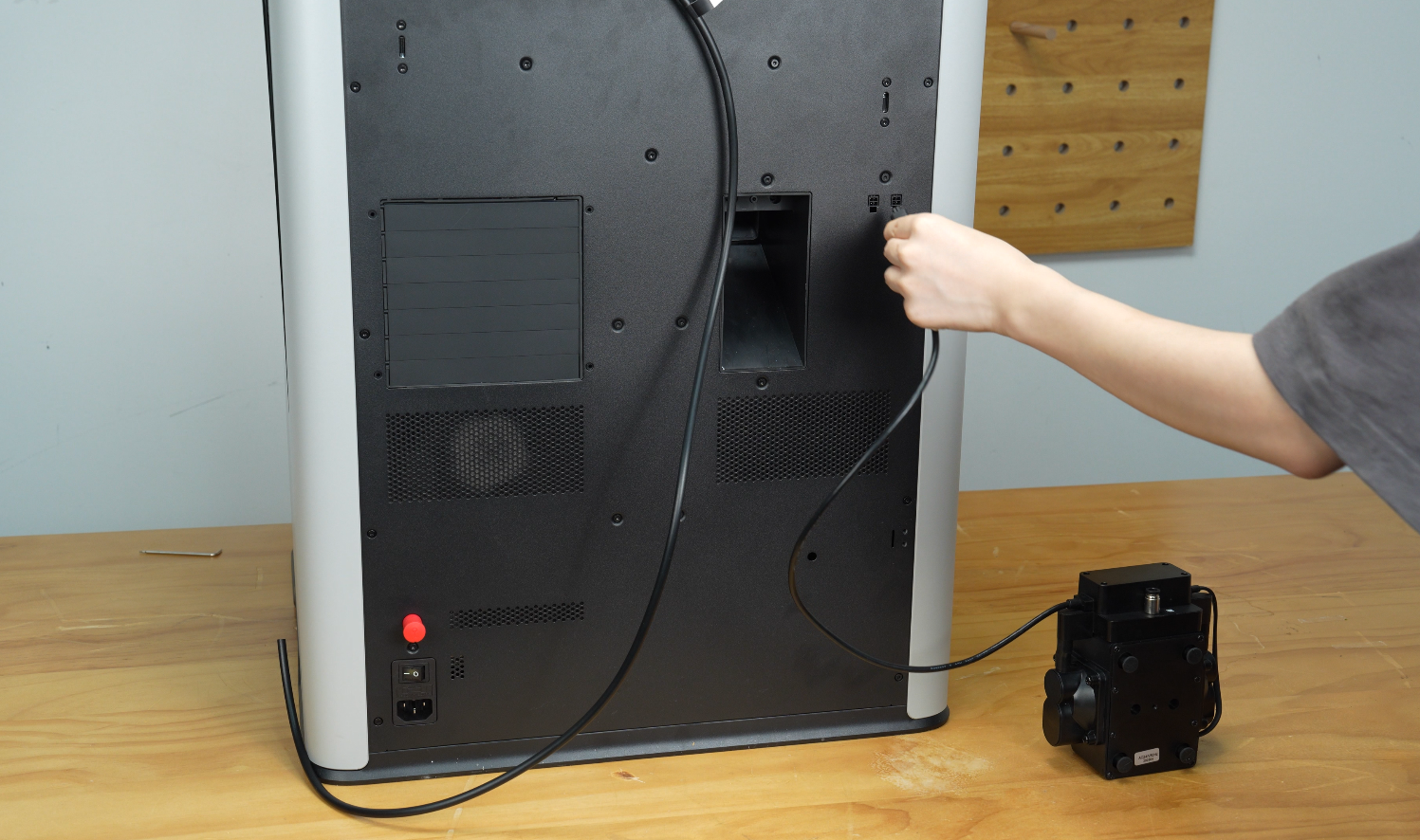
- Connect the remaining end of the air assist tube to the air pump interface.

- After inserting it into place, gently wiggle the air assist tube to confirm that the tube is fully connected.

- Lay the air pump flat on the table.

Note: The air pump might vibrate, so it is important to ensure it is placed in a safe place, so it does not fall down and get damaged.
Install the Smoke Ventilation Pipe
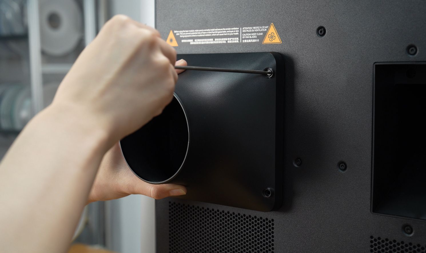
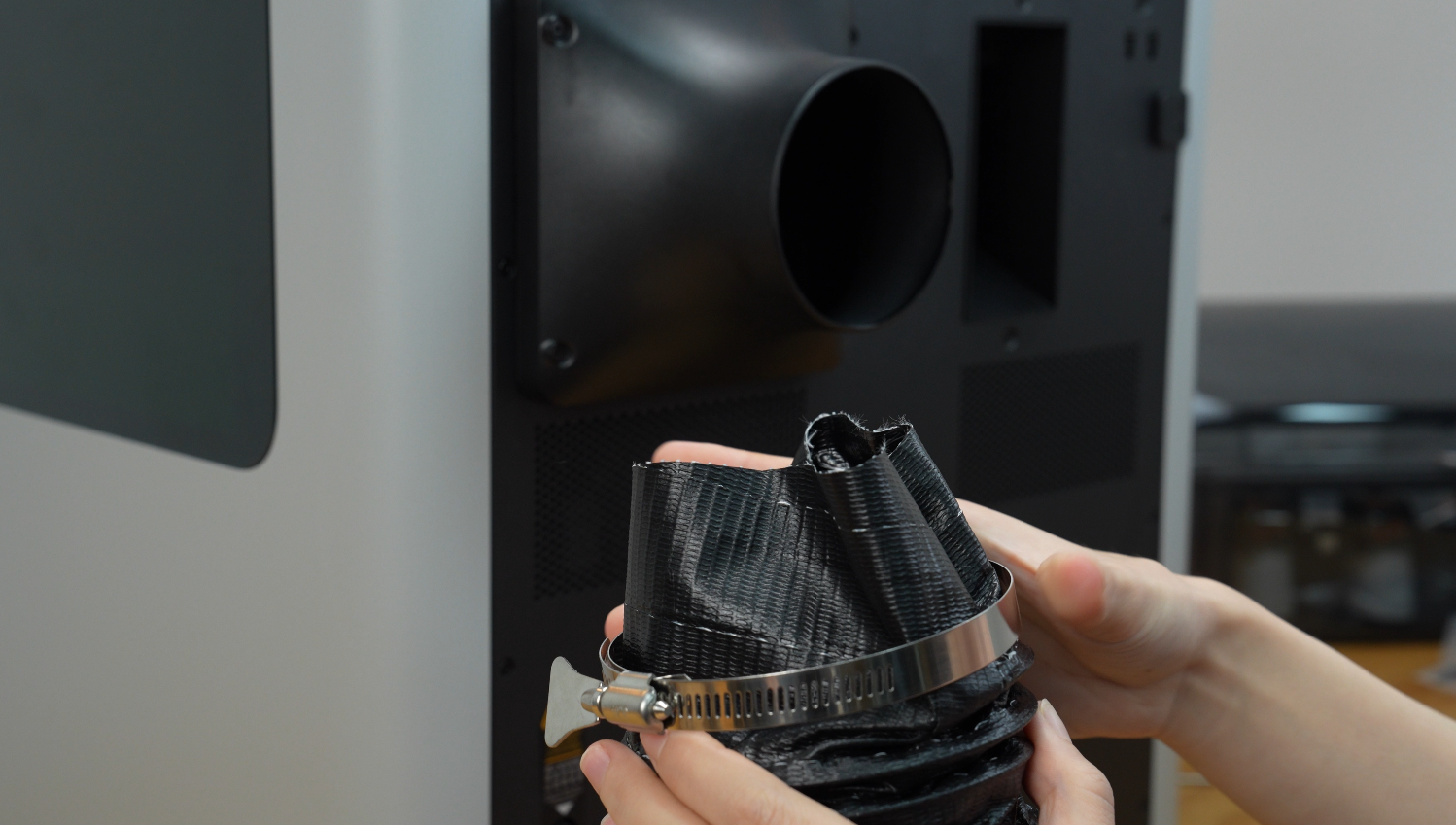
- Place the ventilation pipe adapter over the chamber exhaust fan at the back of the printer and tighten the four screws.
 |
 |
- Put the pipe clamp on one end of the smoke ventilation pipe and install the pipe over the ventilation pipe adapter so that it completely covers the adapter. Tighten the pipe clamp over the portion of the ventilation pipe which is fit over the ventilation pipe adapter until snug.
 |
 |
- After installation, firmly pull on the ventilation pipe to confirm that it is completely secured.

Install the Emergency Stop Button
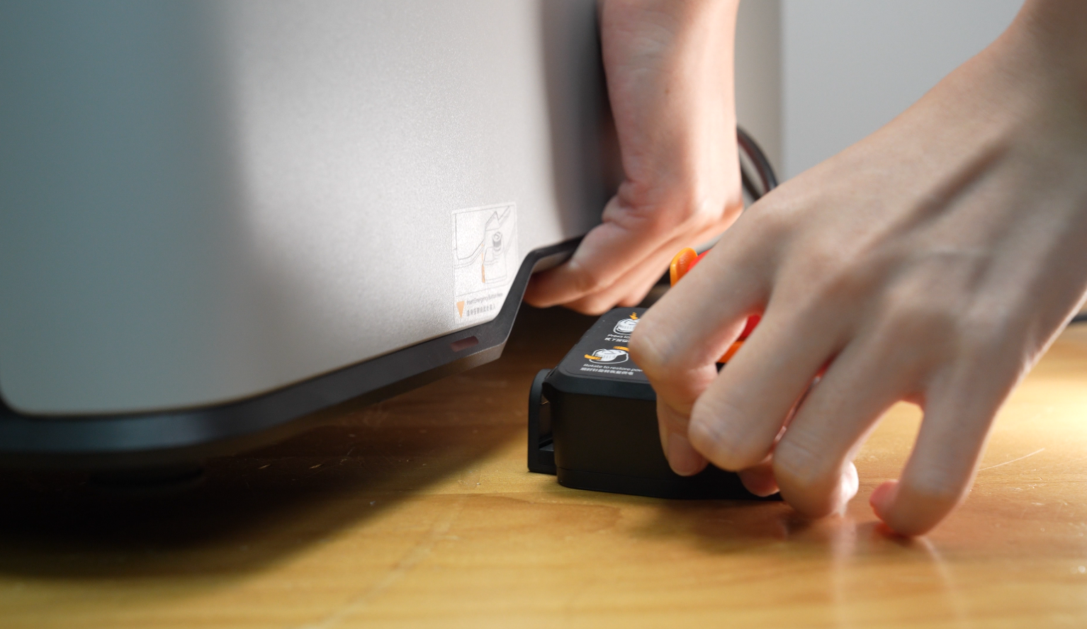
- Check that the safety key is inserted into the emergency stop button;

- Install the emergency stop button by lifting the printer and placing the emergency stop button clip under the lip of the printer.
 |
 |
- Remove the power safety key from the back of the printer and plug in the emergency stop button cable.
 |
 |
Unpack the Laser Module
- Open the laser module;

- Take out the quick start guide and spare laser lens;
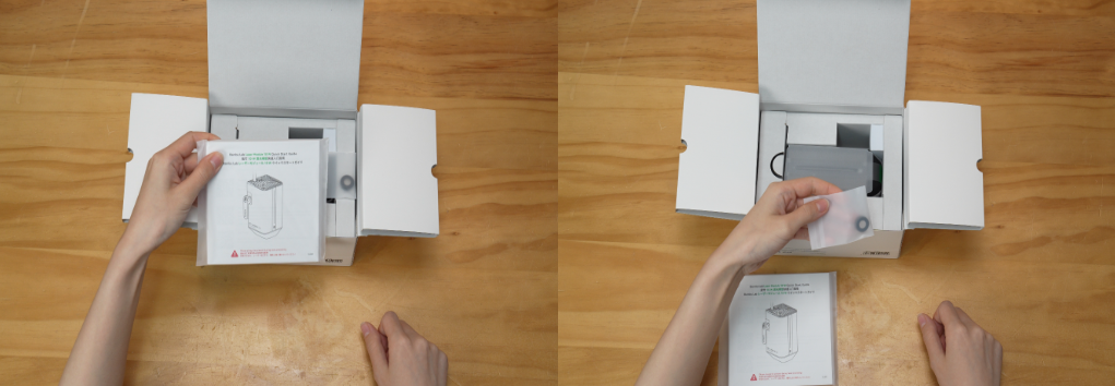
- Pull out the left insert cards;

- Take out the laser module;

- Remove the protective cover of the laser module;

- Remove the transparent sticker on the surface.

Install the Laser Module
Grip the lower part of the toolhead front cover and pull forward to remove it.
Next, remove the rotating indicator wheel.

Align the laser module with the slot, slide it in along the track, and press the latch to secure it.

Connect the cable to the toolhead.

Note: Before printing, be sure to remove the laser protective film and check that there are no foreign objects or print debris inside the chamber to avoid a fire hazard.
Connect one end of the air tube to the laser module and the other end to the pneumatic fitting on the back of the printer.


After installation, it should look as shown below:

Birdseye camera Setup
- Make sure there are no objects blocking the heatbed, especially the calibration marks highlighted in the image below.

- Enter the BirdsEye Camera Setup page from the HMS page or “Settings-Toolbox”;

Install the Laser Platform
- Install the slats on the laser platform by pressing them into the slots on both sides. A “click” sound suggests that a slat is in place. Place a slat every 4 slots as shown in the picture.


- Place the laser platform on the heatbed, and make sure to align the two markers of the laser platform and the stoppers of the heatbed.


Install the Top Laser Protection Plate
- Remove the protective film from the top laser protection plate.

- Place the top laser protection plate into the recessed opening at the top of the printer.

Laser Module Setup
- Place the laser focus calibration card in the rearward middle position of the laser platform, as shown in the image below.

- Enter the laser module setup page from the HMS page or “Settings-Toolbox”;

- After the laser module setup is completed, open the front door and remove the laser focus calibration card.

For more information about laser focus calibration, please refer to Laser Focus Calibration Introduction.
Appendix
- For H2S laser upgrade FAQs, please refer to Laser Upgrade Kit FAQ.
- For laser module installation guide, please refer to Laser Module Installation Guide.
Notas Finais
We hope this guide has provided clear and practical support.
If the issue remains unresolved, please submit a support ticket and include your recent printer logs and additional pictures or other details. Our customer support team will review your request and provide detailed assistance.
You can also visit Bambu AI, which can instantly answer common questions and provide you with operational guidance.


