
Replace H2 Series Regular Idler Pulley
Bambu Lab H2S • Série Comercial H2
Replace H2 Series Regular Idler Pulley
Note: This page uses the H2D machine as an example. The replacement steps are exactly the same for the H2S and H2C.
Kit Contents
Compatible with H2 series (H2D, H2S, and H2C). The regular idler pulley kit includes:
-
Regular Idler Pulley ×1
-
Idler Shaft ×1(long)
-
Tensioner Idler Shaft ×1(short)
-
Graphite Gasket ×2

Supported Models
H2D, H2S, H2C, H2D Pro
When to Replace
-
Abnormal noise from the regular idler pulley
-
The idler or its shaft is damaged
Ferramentas Necessárias
- H2.0 hex driver
- H1.5 hex driver
Lift the Enclosure Top Frame
Passo 1. Remove the Rear Panel
Remove 11 sheet-metal self-tapping screws (ST3×6) and 12 plastic self-tapping screws (BT3×8).
It is strongly recommended to prepare two small containers in advance to separate the two screw types and avoid mix-ups.
-
Use an H2.0 hex driver to remove the 11 × ST3×6 (red circles in the below image).
-
Use an H2.0 hex driver to remove the 12 × BT3×8 (green rectangles in the below image).
-
The yellow marker indicates the fixing screws for external spool (M3×12).

- Press the pneumatic fitting to clear interference, then tilt the rear panel back slightly and lift it out.

For detailed instructions, see Replace H2 Series Rear Panel .
Passo 2. H2S Right Side Panel
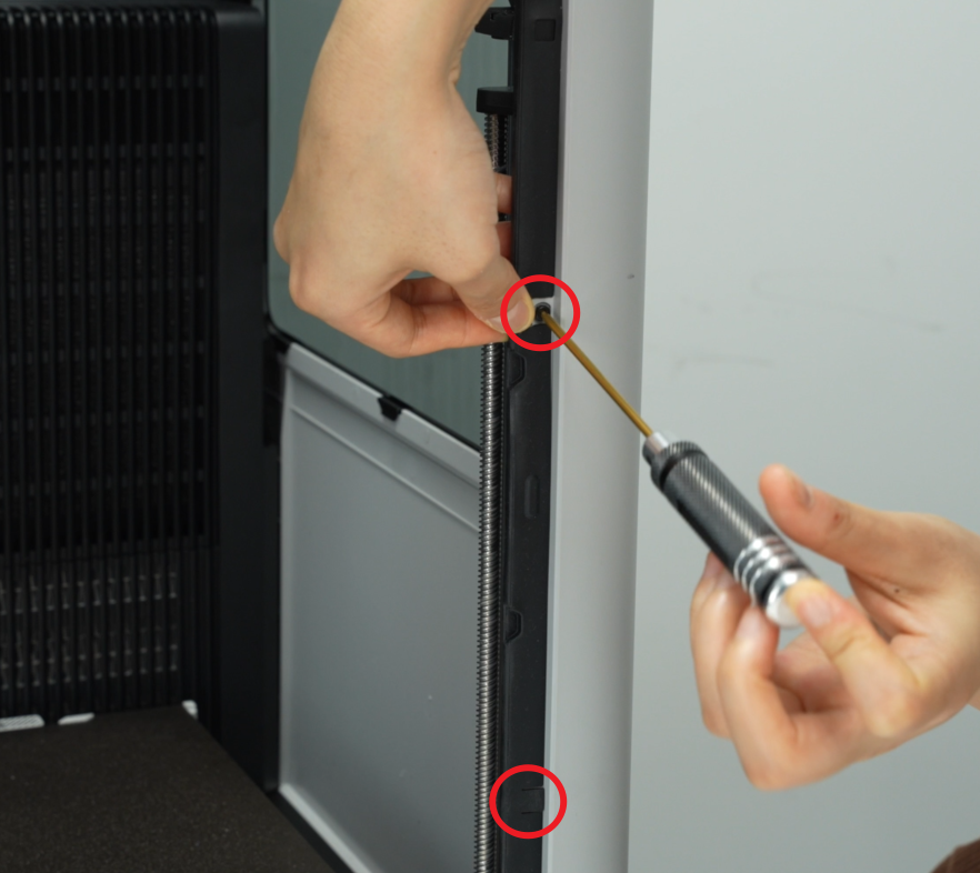
- Open the slit in the silicone strip and remove the two ST3×3 screws with an H2.0 hex driver.
If the slit is hard to lift, use the handle/short arm of the hex driver to gently pry it open. Avoid scratching the panel.
 |
 |
|---|
- From the inside of the panel, remove the two BT3×8 screws with an H2.0 hex driver.

- Remove the BT3×8 screw that secures the crossbeam to the side.

- Grip the rear edge of the right panel with both hands and pull outward to release the rear clip. Then release the top clip and the front-door-side clip in sequence.
Tip: You can use an H2.0 driver as a lever to help release the top clip.
 |
 |
 |
|---|
For more detail, see Replace H2S Left/Right Side Panel
Passo 3. Remove the Left Side Panel and the Front Door
- Use an H2.0 hex driver to remove the four door screws (M3×3, 10 mm nut diameter), two at the top and two at the bottom. Support the glass with one hand and lift the door away.
Hold the front door securely to prevent it from dropping.
 |
 |
|---|
- One side-panel screw sits behind the auxiliary-parts cooling fan, so remove the fan first. The fan is held by two upper rubber rivets and two lower screws. Remove the two lower BT3×16 screws with an H2.0 hex driver, then pull the fan straight out to free the two rubber rivets. Place the fan on the heatbed; do not disconnect it from the MC board.

- Use an H2.0 hex driver to remove two BT3×8 screws on the top frame and one BT3×8 screw on the crossbeam.
 |
 |
|---|
- Two M3×3 screws are fixed to the front pillar and hidden under the silicone strip. Pry open the strip at the cutout to expose and remove the screws.
 |
 |
 |
|---|
For more detail, see Replace H2S Left/Right Side Panel
Passo 4. Remove the Filament Cutter Stoppers
Remove the four screws securing the filament cutter stoppers using an H2.0 hex driver (red circles: BT2.6×8; blue squares: M2.5×5).
 |
 |
|---|
Passo 5. Disconnect AP-board Cables
Unplug the following (see numbered callouts):
- MMC-AP communication cable (No. 1)
- MC–AP power supply cable (No. 2)
- Live view camera connector (No. 3)
- USB-C cable (No. 4)
- TH board power supply cable(No. 5)

Passo 6. Disconnect the Front-Pillar Hall Sensor
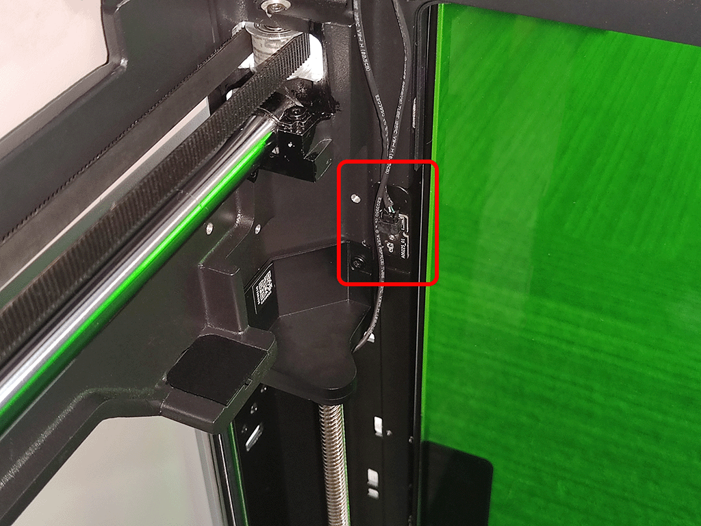
On the pillar next to the Start/Pause button, unplug the Hall-sensor connector to avoid pulling it during later steps.
 |
 |
|---|
Passo 7. Peel the Acetate Tape on the Front Pillar
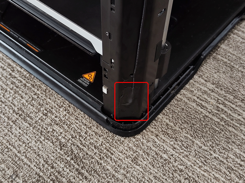
Peel the acetate tape at the bottom of the Start/Pause side, straighten the cable bundle, and leave some slack for the next steps.
 |
 |
|---|
Passo 8. Release the Live-View camera FFC on the Side
On the USB port board side, locate the Live-View camera FFC retention tape and carefully peel it to free the cable.

Passo 9. Release the Cable Latch
Release the cable latch (located beside the filament buffer) to prevent interference with the following procedures.

Passo 10. Lift the Enclosure Top Frame
- Use an H2.0 hex driver to remove the eight fixing screws (M3x10), two screws for each pillar;
 |
 |
|---|---|
 |
 |
- Lift the enclosure top frame slightly and nudge it away from the idler side to create working clearance for the idler-shaft screw.
Reminder: You don’t need to fully lift the cover—just enough space to work is fine. Mind all cables; avoid pulling or stressing them.


Remove the Regular Idler Pulley
- Using an H2.0 hex driver, remove the two M3×8 screws from the belt clamp on one side of the toolhead to release the belt.

- Using an H2.0 hex driver, unthread the idler shaft as far as it will turn. Then gently wiggle it left–right with a small angle while pulling straight out along the axis.
 |
 |
|---|
Note: For the deep-bore side near the USB port board side, suggested sequence
Still start with the H2.0 hex driver to loosen/unthread the shaft as much as possible.
When it no longer turns / only a small tip is exposed, remove the two M3×6 screws securing the Live-View camera with an H2.0 driver:
- Shift the camera slightly to clear the channel. From the bottom, use a stiff rod thinner than H1.5 to push the shaft straight along its axis.


- Once the shaft is out, support the idler from the side and remove it together with the graphite gasket.
Install the New Regular Idler Pulley
- Apply a tiny amount of grease to the idler’s inner race/end face. Keep lubricant away from the belt contact surface. Stick a graphite gasket to the matching face of the idler first so it won’t slip during placement. Apply grease at the locations shown below:

Note: Install graphite washers on both sides of the idler.

- Place the new regular idler back into the original mount. Insert the idler shaft and tighten with an H2.0 driver.

Note: Be careful not to let the graphite gasket fall during insertion.
- Reinstall the belt clamp on the toolhead and tighten the two M3×8 screws with an H2.0 hex driver.
Note: The belt is under tension. Press the belt clamp inward by hand while tightening the two M3×8 screws with the H2.0 hex driver.
Re-install the Enclosure Top Frame
Passo 1. Install the Enclosure Top Frame
- As shown, slide the enclosure top frame into the frame. Align with the cable run at the rear-left as a reference, then lower it into position.
Note: Before lowering, make sure all cables are clear of edges to avoid pinching any wires.
 |
 |
 |
|---|
- Use an H2.0 hex driver to tighten the eight fixing screws (M3x10), two screws for each pillar;
|
|
|---|---|
|
|
Passo 2. Re-engage the cable latch
Align the keyed connector and press the latch until it locks. Perform a gentle tug test to ensure it won’t come loose.
Passo 3. Re-tape the Live-View camera FFC
On the USB port board side, locate the FFC and press the retention tape back down along the original marks.
Passo 4. Re-tape the acetate tape on the front pillar
Straighten and dress the cable bundle. Collect any extra length neatly along the original path and secure it with acetate tape.
|
|
|---|
Passo 5. Reconnect the front-pillar Hall sensor
On the pillar next to the Start/Pause button, plug the Hall-sensor connector back in until it clicks and is secure. Make sure it won’t get tugged loose later.
|
|
|---|
Passo 6. Reconnect AP-board cables
Reconnect in this order (see numbered callouts):
- MMC-AP communication cable (No. 1)
- MC–AP power supply cable (No. 2)
- Live view camera connector (No. 3)
- USB-C cable (No. 4)
- TH board power supply cable(No. 5)
Passo 7. Reinstall the filament cutter stoppers, side panels, front door, and rear panel
Follow Replace H2S Enclosure Top Frame, and install the filament cutter stoppers, side panels, front door, and rear panel
Belt Tensioning
- Loosen the 4 screws of the belt-tensioner. Loosen the screw 1-2 turns; do not remove it.
 |
 |
|---|
- Gently move the toolhead back and forth several times, and finally move it to the rear end of the printer.
- Tighten the 4 screws again. The spring system in the belt-tensioner will tighten the belt to the correct tension.
 |
 |
|---|
IMPORTANT: DO NOT overtighten the belt tensioning screws. Doing that can cause damage and will not provide better results. Simply tighten both screws like any other screws and don’t over-torque them.
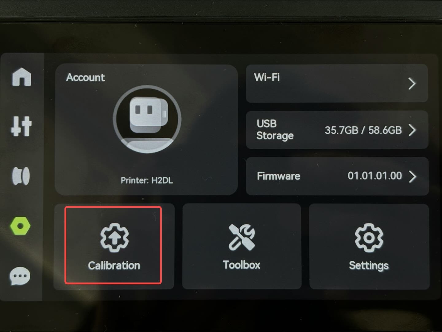
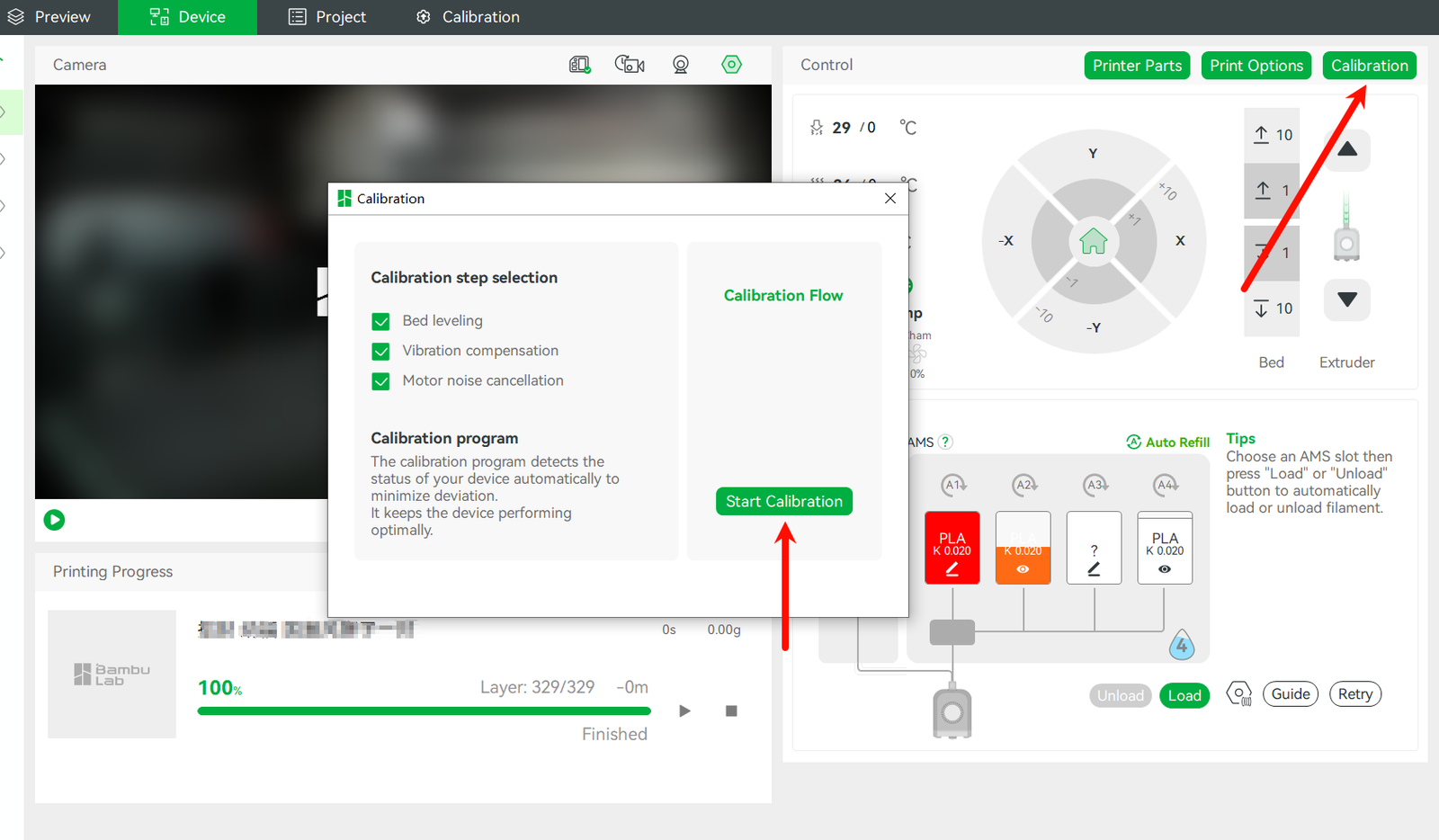
- After the belt tensioning operation is completed, the resonant frequency identification needs to be recalibrated to record the new resonance characteristics of the equipment. And the printer can be calibrated from the screen or Bambu Studio.
 |
 |
|---|
Notas Finais
Esperamos que o guia detalhado fornecido tenha sido útil e informativo.
If this guide does not solve your problem, please submit a chamado técnico, we will answer your questions and provide assistance.
If you have any suggestions or feedback on this Wiki, please leave a message in the comment area. Thank you for your support and attention!


