
Idler Assembly Replacement Guide for the H3C
Bambu Lab H3C • Série Industrial H3
Idler Assembly Replacement Guide for the H3C
Idler Assembly
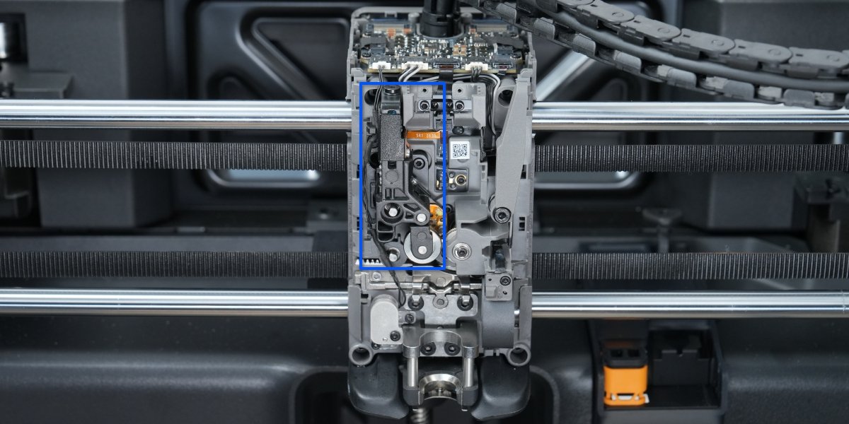
Applicable Printer Model
Bambu Lab H3C
Safety Tips
Before performing any maintenance on the printer and its electronic components (including the Toolhead Cable), turn off the printer and disconnect the power supply to prevent accidental Screen touches or short circuits, which could cause additional electronic damage and safety hazards.

When performing maintenance or troubleshooting on your printer, please first check the temperature of the hotend and heatbed. Avoid operating at high temperatures. If operating at high temperatures is unavoidable, wear insulated gloves to ensure safe and effective maintenance.
Tools and Materials
- H1.5 Allen Key
- H2.0 allen key
- Special Socket
Disassembly and Assembly Tips
When removing and installing the driven wheel assembly, specific position requirements shall be met, and a special sleeve shall be used for adjustment.
During removal: Rotate counterclockwise until it stops, so that the driven wheel is at the adaptation position corresponding to a filament diameter of 1.75 mm.
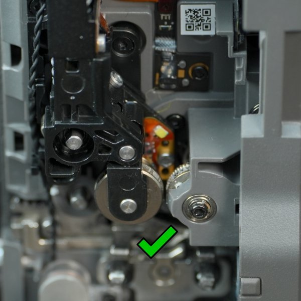
1.75 mm filament diameter position

2.85 mm filament diameter position

Fully unlock the position
**During installation:**Adjust the orientation of the “tip” of the cam so that it approximately points toward the motor fixing screw located at the lower-left position.

Remove the Idler Assembly
Passo 1. Remove the Toolhead Front Cover and Top Cover
Refer to the WIKI: Toolhead Front Cover Replacement Guide to remove the toolhead front cover and top cover.

Passo 2. Loosen the Connecting Cables
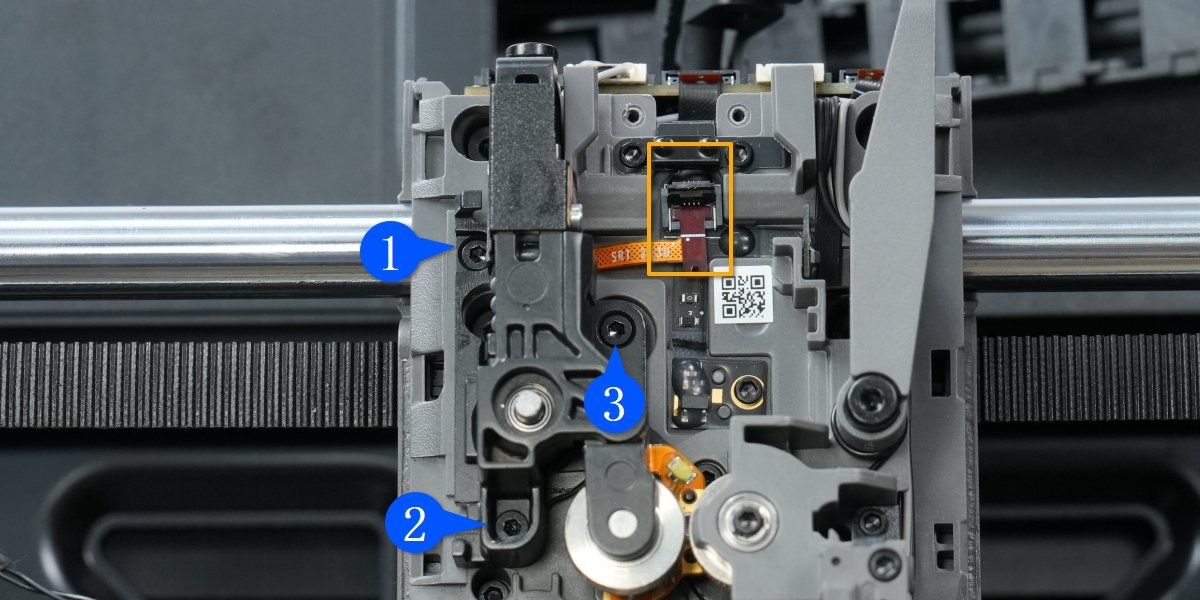
Disconnect the Eddy Current Coils’ plug from the extruder connection board and unclip the cable from the locking tab to completely separate the Eddy Current Coils’ cable from the Idler Assembly.
 |
 |
Use tweezers or a wrench to open the locking tab of the Idler Assembly’s cable connector to release the cable.

Passo 3. Adjust the Flexfeed Cam Position
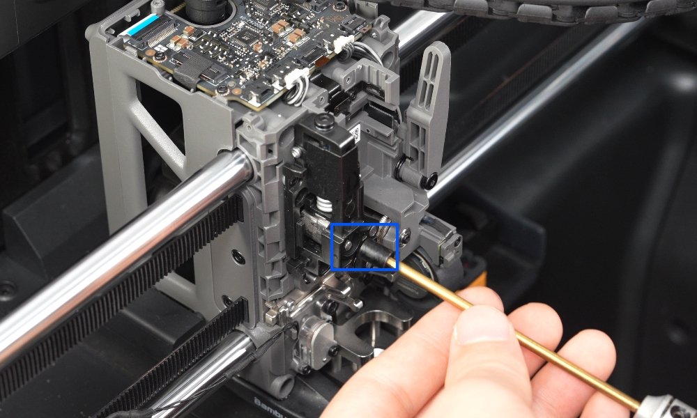
Attach the special socket to the H2.0 allen key and turn the FlexFeed Cam until it is in the locked position (i.e., 1.75mm filament diameter state).
 |
 |
Passo 4. Remove the Idler Assembly
Use an H1.5 allen key to remove 3 screws, then take off the Idler Assembly. (The cable connector cover was opened in Passo 2)
Install the Idler Assembly
Passo 1. Adjust the Cam Position, Check Bearings
Before installing the Idler Assembly, ensure the FlexFeed Cam is in the following position. (If you did not turn it after removing the Idler Assembly, you can skip this step). Check the bearings: The FlexFeed Cam or the Idler Assembly must have exactly one bearing in one of the two positions. Remove any extra bearings or add one if missing.
 |
 |
Passo 2. Install the Idler Assembly
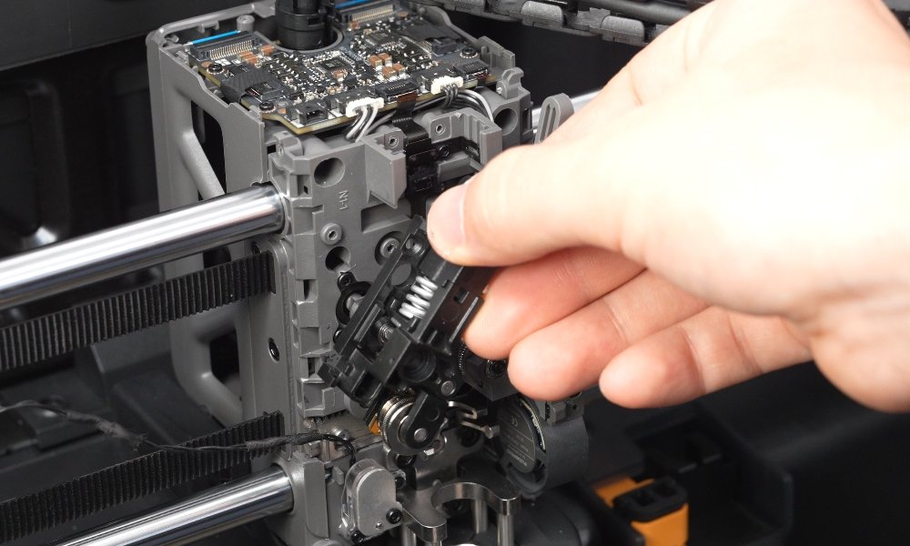
Install the Idler Assembly onto the toolhead, tilting it to align with the cam, then straighten it.
 |
 |
Secure the Idler Assembly with 3 screws, then connect the cable and close the cover.
Passo 3. Connect the Cable
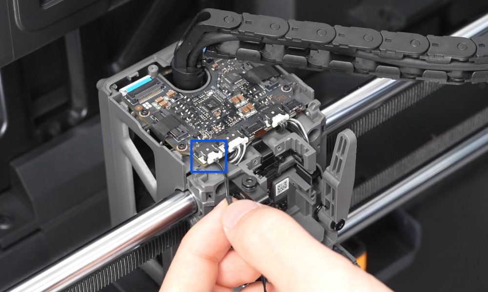
Reconnect the Eddy Current Coils’ plug to the extruder connection board, and guide the cable (where it’s wrapped with protective tape) into the Idler’s locking tab.
 |
 |
Passo 4. Install the Toolhead Front Cover and Top Cover
Refer to the WIKI: Toolhead Shell Replacement Guide, install the toolhead top cover and front cover.

Passo 5. Run the Calibration (for Replacement Only)
Note: If you are not replacing a part that requires recalibration, do not run the Gcode. This may cause damage or unpredictable errors.
After replacing this component, calibration is required. Please refer to the dedicated wiki: “ToolLock motor and FlexFeed motor have not been calibrated. Please scan the QR code and refer to the Wiki to complete the calibration before performing any other operations.” to finish the calibration procedure.
Verify Functionality
- If a part has been replaced, perform the calibration after setting up the printer.
- If parts have been disassembled and reassembled, run the tool change procedure once, and the operation is complete.
Notas Finais
We hope this guide has provided clear and practical support.
If the issue remains unresolved, please submit a support ticket and include your recent printer logs and additional pictures or other details. Our customer support team will review your request and provide detailed assistance.
You can also visit Bambu AI, which can instantly answer common questions and provide you with operational guidance.


