
Power Socket Replacement Guide
Bambu Lab H3C • Série Industrial H3
Power Socket Replacement Guide
Power Switch Assembly
The Power Switch Assembly is a power cord socket installed on the back of the printer, which is the interface for the external power supply to the printer. It includes a power cord socket, a switch to control the printer’s power, and some cables.
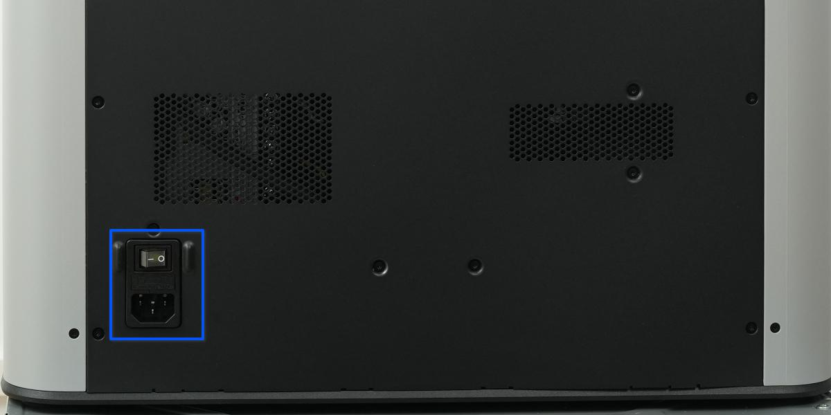
When to Replace
- The power indicator light does not turn on properly.
- The Power Switch Assembly shows signs of burning.
- Structural component damage
Safety Tips
Before performing any maintenance on the printer and its electronic components (including the Toolhead Cable), turn off the printer and disconnect the power supply to prevent accidental Screen touches or short circuits, which could cause additional electronic damage and safety hazards.

When performing maintenance or troubleshooting on your printer, please first check the temperature of the hotend and heatbed. Avoid operating at high temperatures. If operating at high temperatures is unavoidable, wear insulated gloves to ensure safe and effective maintenance.
Tools and Materials
- H2.0 allen key
Remove the Power Switch Assembly
Passo 1. Remove the Rear Panel and Purge Chute
Refer to the wiki: Purge Chute Replacement Guide to remove the rear panel and purge chute.

Passo 2. Remove the Cables
Using the H2.0 Allen key, remove the ground wire screw from the upright and disconnect the ground wire.
Use a Phillips screwdriver to loosen the screws on the input terminals of the power and AC board, and unplug the power connector.
Unclip the cables from the two cable clips.

Passo 3. Remove the Power Switch Assembly
Use the H2.0 allen key to remove 2 screws and take off the Power Switch Assembly.

Install the Power Switch Assembly
Passo 1. Install the Switch Assembly
Align the mounting holes and dowels, install the Power Switch Assembly, and secure it with the two screws.
 |
|
Passo 2. Connect the Cables
Connect the ground wire to the screw hole on the upright and secure it with one ground wire screw and washer.
Connect the power cables to the corresponding input terminals on the power supply and AC board, and tighten the screws.
Passo 3. Reinstall the Purge Chute and Rear Panel
Refer to the wiki: Purge Chute Replacement Guide to complete the installation of the purge chute, rear panel, and other accessories.

Verify Functionality
Passo 1. Connect the power, turn on the printer, and confirm that the operation interface can be accessed successfully on the screen.
Passo 2. Set the bed temperature to 50°C and confirm that the heatbed can heat up normally.
Notas Finais
We hope this guide has provided clear and practical support.
If the issue remains unresolved, please submit a support ticket and include your recent printer logs and additional pictures or other details. Our customer support team will review your request and provide detailed assistance.
You can also visit Bambu AI, which can instantly answer common questions and provide you with operational guidance.


