
Tool Reader Replacement Guide
Bambu Lab H3C • Série Industrial H3
Tool Reader Replacement Guide
Tool Reader
This accessory uses a configured sensor to automatically identify the tools it holds.

When to Replace
The connection is normal, but tool identification is abnormal or reports an error.
Tools and Materials
- H1.5 Allen Key
- Tweezers
Safety Tips
Before performing any maintenance on the printer and its electronic components (including the Toolhead Cable), turn off the printer and disconnect the power supply to prevent accidental Screen touches or short circuits, which could cause additional electronic damage and safety hazards.

When performing maintenance or troubleshooting on your printer, please first check the temperature of the hotend and heatbed. Avoid operating at high temperatures. If operating at high temperatures is unavoidable, wear insulated gloves to ensure safe and effective maintenance.
Remove the Tool Reader
Passo 1. Remove the Toolhead Cover
Please refer to the dedicated Toolhead Front Cover Replacement Guide for the H3C to remove the toolhead front cover and top cover.
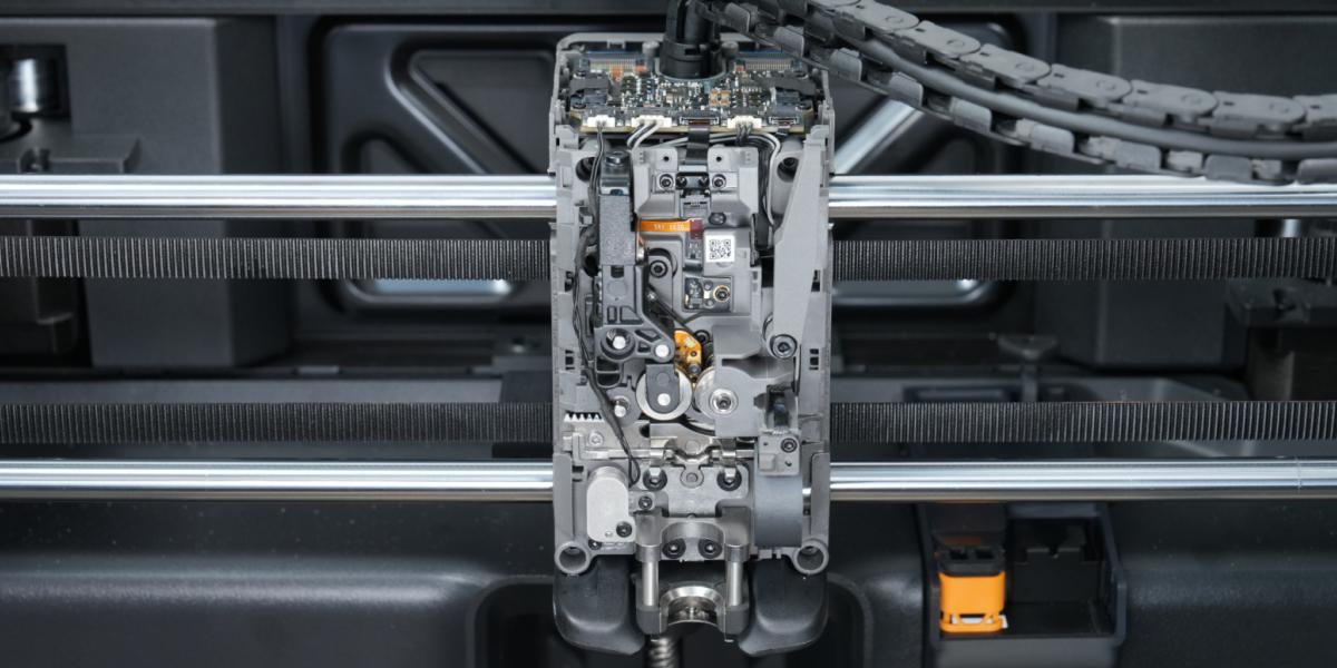
Passo 2. Disconnect the Ribbon Cable
Use an H1.5 Allen key to remove the two screws, then remove the Tool Reader’s metal pressure plate.
 |
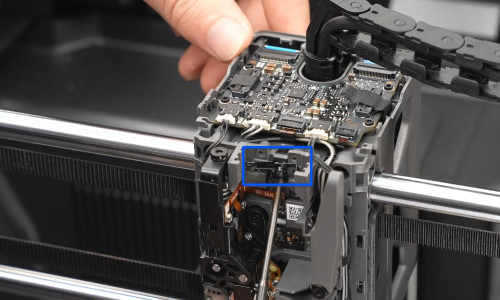 |
Using tweezers or an Allen key, gently open the connector cover on the Tool Reader assembly, then carefully disconnect the Idler Assembly ribbon cable from the connector.
 |
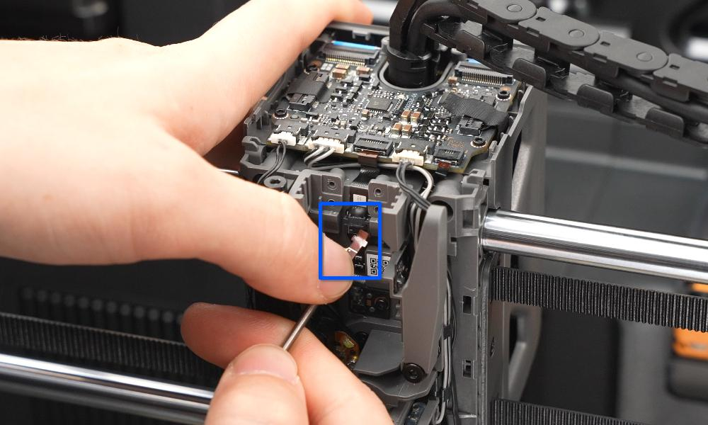 |
Manually open the connector cover on the extruder connection board and disconnect the ribbon cable of the Tool Reader assembly from the connector.
 |
 |
Passo 3. Remove the Tool Reader
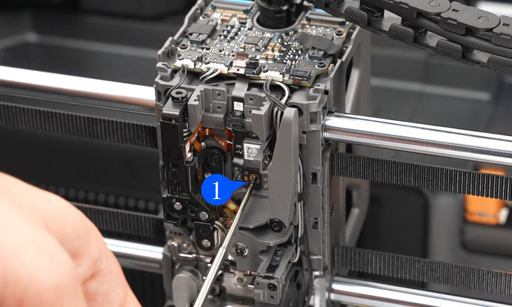
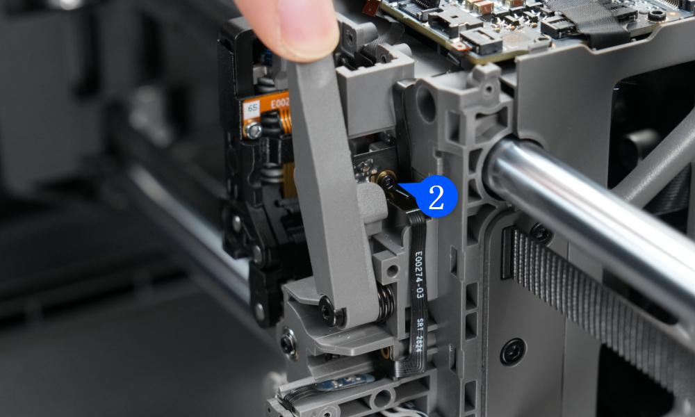
Use an H1.5 Allen key to remove the two screws.
 |
 |
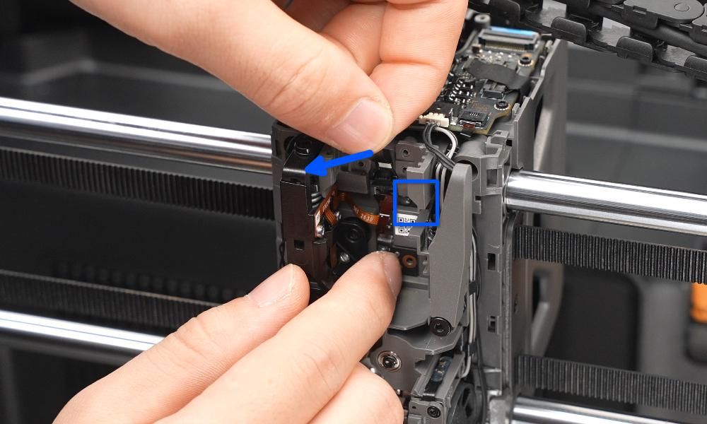
The Tool Reader is also secured by an adhesive backing. Gently peel it off the toolhead by pinching its ribbon cable with your fingers. Be careful not to apply too much force at the right-side split point to avoid damage.
 |
 |
Install the Tool Reader
Passo 1. Install the Tool Reader
Tip: When installing a new Tool Reader, you need to first remove the protective adhesive film from the back of the ribbon cable so it can adhere well to the toolhead.
Remove the protective adhesive film, then align with the installation slot and positioning pin to attach the Tool Reader to the toolhead.
 |
 |
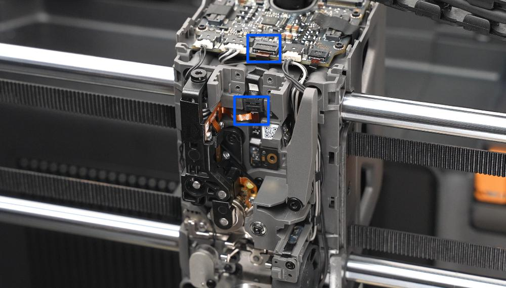
First, connect the ribbon cable from the Idler Assembly to the Tool Reader’s connector and close the cover. Then, connect the Tool Reader’s ribbon cable to the extruder connection board.
 |
 |
Passo 2. Secure the Tool Reader Screws
Use an H1.5 Allen key to secure the two screws. Note that the screw at position 2 might be attracted by the magnet on the filament cutting component, so be careful during installation.
|
|
Install the metal pressure plate and secure it with the two screws. You can first insert one screw through the pressure plate’s screw hole, then position the screw and pressure plate together. Finally, tighten the screws to secure the pressure plate.
 |
 |
Passo 3. Install the Toolhead Rear Cover
Please refer to the wiki: Toolhead Cover Replacement Guide to install the toolhead front cover and top cover.

Verify Functionality
Connect the power, turn on the printer, and perform a ‘Fetch PrintTool’ operation. If it completes successfully, you are done.

If you encounter any issues, please retrace your steps and check all connections before retrying. If the problem persists, please contact the Bambu Lab support team for further assistance.
Notas Finais
We hope this guide has provided clear and practical support.
If the issue remains unresolved, please submit a support ticket and include your recent printer logs and additional pictures or other details. Our customer support team will review your request and provide detailed assistance.
You can also visit Bambu AI, which can instantly answer common questions and provide you with operational guidance.


