
Power Supply Replacement Guide for the P2S
Bambu Lab P2S • Série Performance P2
Power Supply Replacement Guide for the P2S
Power Supply
The power supply of P2s is a device that converts an AC input voltage of 100–240 V into a 24 V DC output. It provides stable, clean, and compliant DC power to the entire printer, except for the heatbed.

The accessories of the power supply include the following:
- Power supply* 1
- BT2x5 screw* 2
When to Use This Guide
- The power supply shows clear physical damage, such as a broken connector, detached components, or burn marks.
- Bambu Lab technical support has confirmed that the power supply needs to be replaced.
Aviso de Segurança
IMPORTANT!
Always power off and disconnect power on the printer before performing maintenance work. Not doing so means there is a risk of electric shock, short circuit, and damage to the printer or surrounding area.
When a maintenance task necessitates the printer being powered on, use insulated gloves for safety and pay special care not to pinch, damage, or put pressure on any exposed wires, connectors, or circuit boards. Additionally, the nozzle can be extremely hot so never touch it with exposed skin.
If you have any questions or concerns related to the above or the steps in this guide, please open a new ticket in our Support Page for assistance.
Removing the Power Supply
Passo 1: Remove the PTFE Tube Bracket, Filament Buffer, and Rear Panel
Refer to the following Wiki disassembly guides to remove the PTFE tube bracket, filament buffer, and rear panel in sequence.
Replace the PTFE tube bracket
Replace the filament buffer
Replace the rear panel
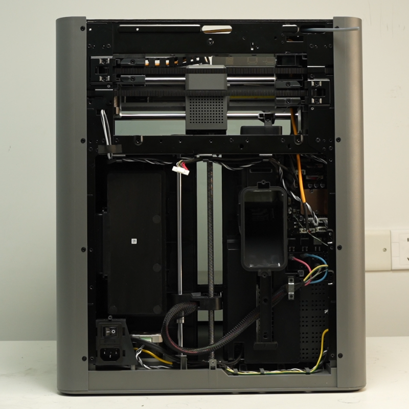
Passo 2: Remove the Purge Chute
Use an H1.5 Allen key to remove the four fixing screws (BT2×5), then remove the purge chute.

Passo 3: Remove the Power Supply Cover
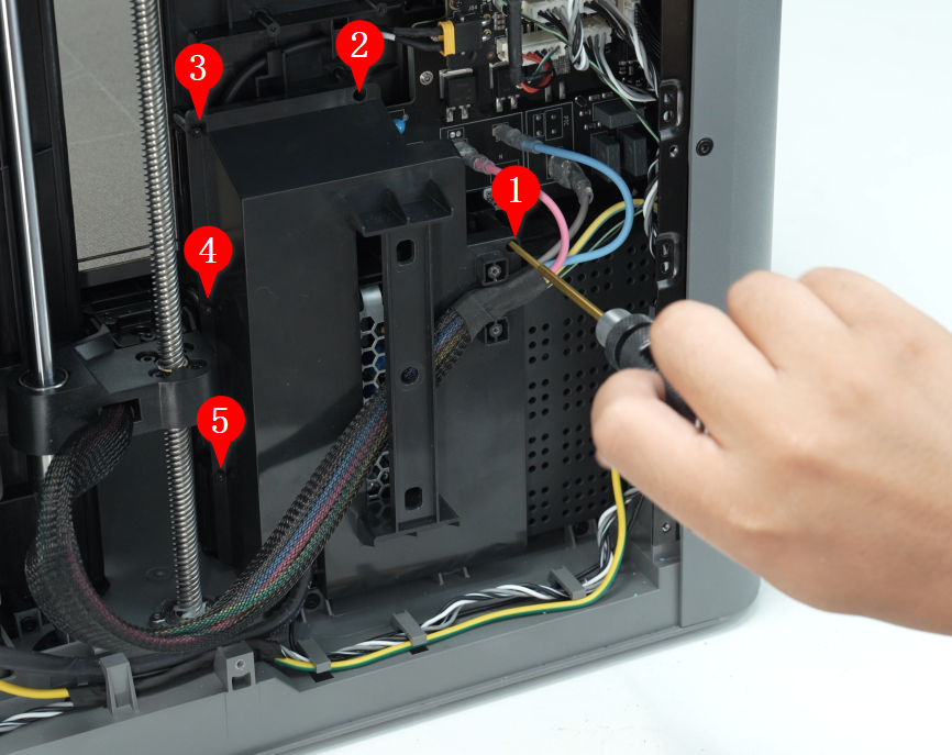
Use an H1.5 Allen key to remove the two screws (BT2×5) securing the heatbed wire clamp, then remove the clamp.

Use an H1.5 Allen key to remove the five power supply protection cover fixing screws (BT2×5) one by one. Then remove the power supply protection cover and set it aside. The heatbed wires do not need to be removed from the power supply cover, as this will facilitate the subsequent removal of the power supply.
 |
 |
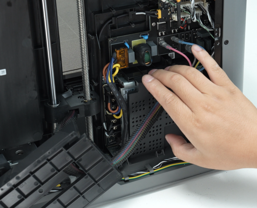
Slide the power supply cover from right to left and then remove it.
 |
 |
Passo 4: Remove the Power Supply
Use a Phillips screwdriver to loosen the screws on the power cable connector and remove the five cables from the power supply one by one.
 |
 |
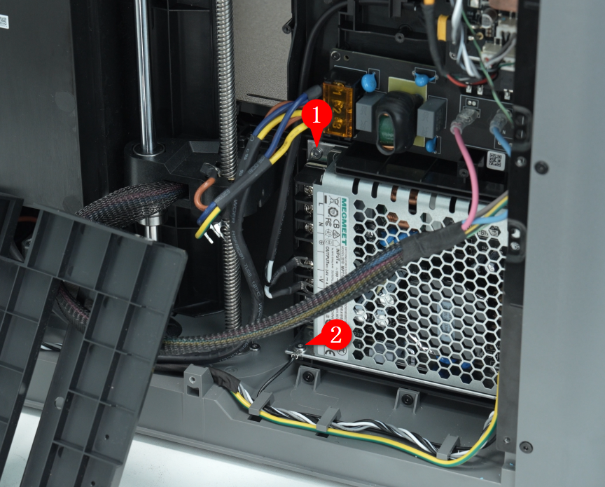
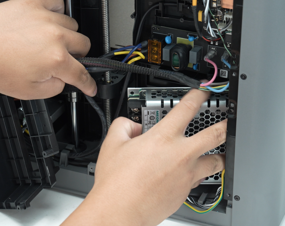
Use an H2.0 Allen key to remove the two power supply fixing screws (BT2x5), and then remove the power supply.
 |
 |
Installing the Power Supply
Passo 1: Install the Power Supply
Install the power supply into the liner and tighten the two fixing screws (BT2x5) using an H2.0 Allen key.
Note: The bottom fixing screw must also secure the ground wire.
 |
|
Insert the five cables into the power ports in sequence as shown in the figure below. From top to bottom, the colors are as follows: brown (live wire), blue (neutral wire), yellow-green (ground wire), black (24V negative), white (24V positive). Then tighten the screws with a Phillips screwdriver. You can hold the cables with your hand when tightening the screws with the screwdriver to prevent the cables from coming loose.
|
 |
Passo 2: Install the Power Supply Cover
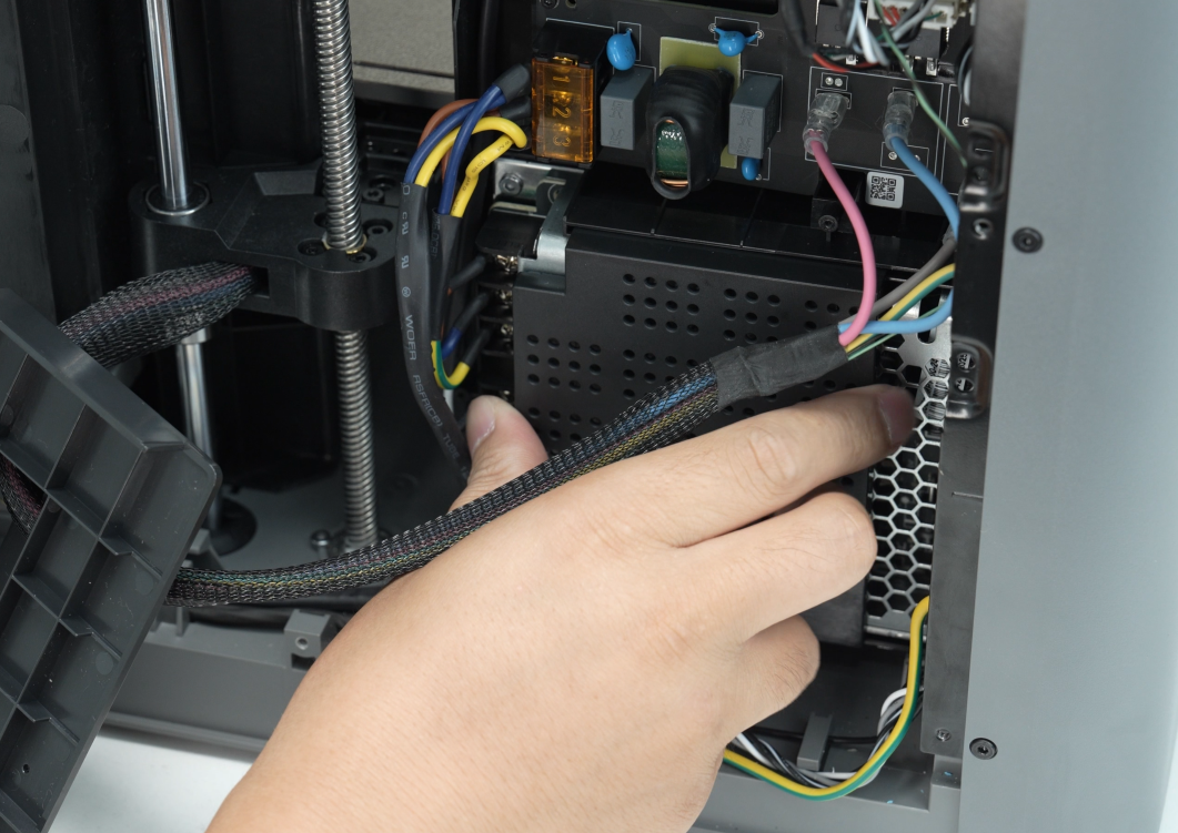
First, install the power cover on the left side of the power supply, then push it to the right by hand.
 |
 |
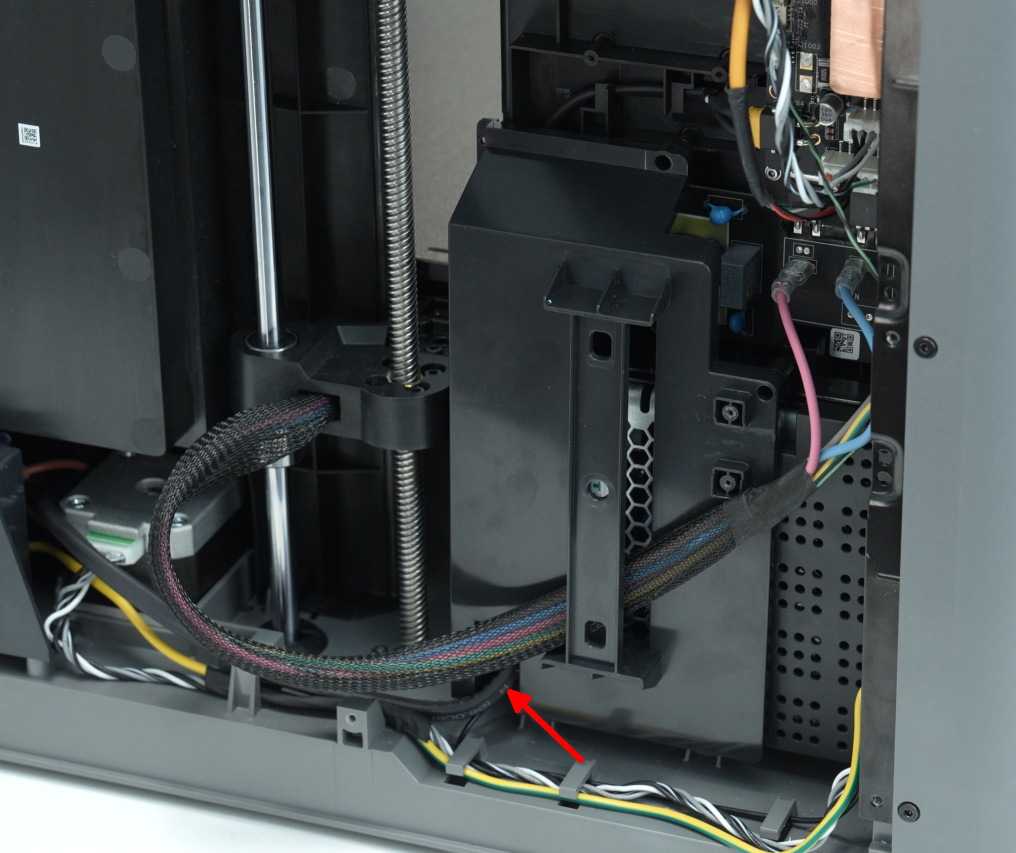
Push the power cord toward the power supply and place it close to the unit. Then, install the power supply protective cover, route the power cable through the groove at the bottom of the power supply protection cover, and then use an H1.5 Allen key to tighten the five BT2×5 screws in sequence.
 |
 |
Insert the heatbed cable into the cable channel on the power supply protection cover, then use an H1.5 Allen key to tighten the two BT2×5 clamping screws.
|
 |
Passo 3: Install the Purge Chute
Align the purge chute with the screw holes on the printer, then use an H1.5 Allen key to tighten the four BT2×5 fixing screws.
Passo 4: Install the Rear Panel, Filament Buffer, and PTFE Tube Bracket
Refer to the following Wiki disassembly sections to install the PTFE tube bracket, filament buffer, and rear panel rear panel, filament buffer, and the PTFE tube bracket in sequence:
Replace the rear panel
Replace the filament buffer
Replace the PTFE tube bracket
Verifying Functionality
Connect the power supply, turn on the printer, and run device calibration. If the calibration is successful, the replacement is complete.
Notas Finais
We hope this guide has provided clear and practical support.
If the issue remains unresolved, please submit a support ticket and include your recent printer logs and additional pictures or other details. Our technical team will review your request and provide detailed assistance.
You can also visit Bambu AI, which can instantly answer common questions and provide you with operational guidance.


