
Printer Cable Pack Replacement Guide for the P2S
Bambu Lab P2S • Série Performance P2
Printer Cable Pack Replacement Guide for the P2S
Printer Cable Pack
The cable pack for the P2S printer and includes four separate internal connection cables:
- AP board to door detection board connection cable
- MC board to buffer connection cable
- MC board power cable
- MC-AC connection cable

When to Use This Guide
- Damage to cables or connectors
Aviso de Segurança
IMPORTANT!
Always power off and disconnect power on the printer before performing maintenance work. Not doing so means there is a risk of electric shock, short circuit, and damage to the printer or surrounding area.
When a maintenance task necessitates the printer being powered on, use insulated gloves for safety and pay special care not to pinch, damage, or put pressure on any exposed wires, connectors, or circuit boards. Additionally, the nozzle can be extremely hot so never touch it with exposed skin.
If you have any questions or concerns related to the above or the steps in this guide, please open a new ticket in our Support Page for assistance.
Replacement of MC-AC cable
Because the MC-AC cable is blocked by the MC board, the MC board needs to be removed when replacing this cable.

Passo 1: Remove the Rear Panel
Refer to this wiki to remove the rear panel: Replace the Rear Panel

Passo 2: Remove the Purge Chute
Use an H1.5 hex wrench to remove the four mounting screws (BT2×5), then take off the purge chute.

Passo 3: Release the MC board
Remove the two heatsink screws and release the cables from the two clips.

Remove the three MC board screws and disconnect the MC-AP board signal cable from the MC board.

Passo 4: Replace the MC-AC cable
Loosen the MC board to fully expose the MC-AC cable, then press the clips on the connector in sequence to remove the MC-AC cable.
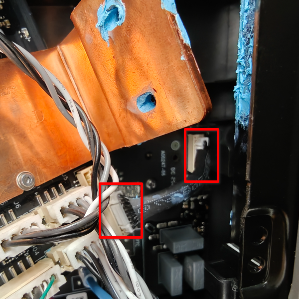
Connect the new MC-AC cable to the two connectors in order, then install the MC board in place according to the screw holes and resecure the screws.
Reassemble the printer by reversing the disassembly steps.
Replacing the MC-Buffer Cable
Passo 1: Remove the Filament Buffer
Use a hex wrench to remove the two screws.

Flip the filament buffer over to expose the cable, press the connector latch by hand, unplug the cable, and remove the buffer.

Passo 2: Remove the Rear Panel
Refer to this wiki to remove the rear panel: Replace the Rear Panel
Passo 3: Replace the MC-Buffer Cable
Release the cable from the two wire clips, then press the connector latch to disconnect the cable from the MC board and remove it.

Connect the new cable to the MC board’s port, ensure it is properly seated, and secure the cable in the two wire clips.

Passo 4: Install the Rear Panel and Filament Buffer
Install the rear panel and filament buffer by referring to this wiki: Replace the Rear Panel
Replace the Door Sensor Board Cable
Passo 1: Disconnect the Cable
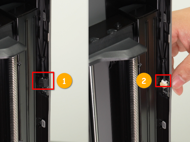
Open the front glass door, locate the sensor switch on the right pillar, remove the covering tape, press the connector latch, and unplug the connector.
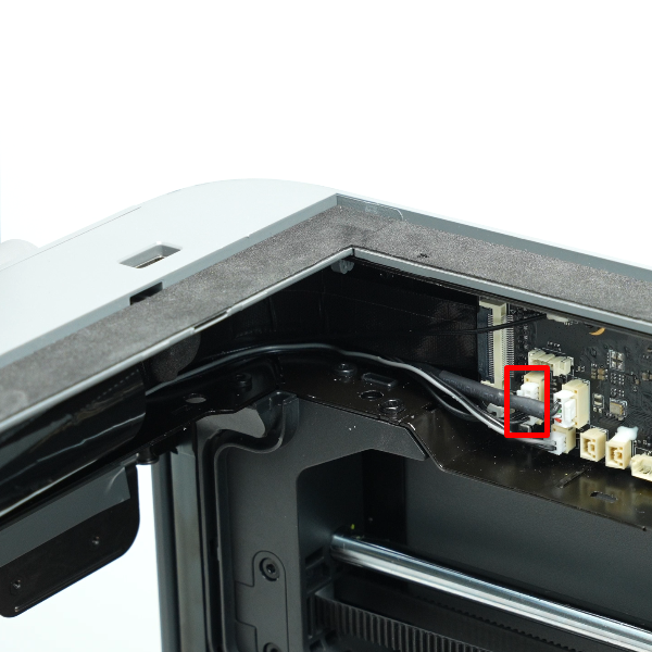
Remove the glass top cover, open the AP board service cover, locate the corresponding connector, press the connector latch, and unplug the connector.
Passo 2: Remove the Cable
On the back side of the front crossbeam, peel off the tape, release the cable from the clips, and remove it.

Passo 3: Install the cable
Connect the new cable to the corresponding connector on the AP board.
Pass the connector for the sensor switch through the hole in the crossbeam and connect it to the sensor switch adapter.

Route the cable into the clips and reapply tape to secure it.
Replace the MC Board Power Cable
Passo 1: Remove the Rear Panel
Refer to this Wiki page to remove the rear panel: Replace Rear Panel
Passo 2: Remove the Purge Chute
Use an H1.5 hex wrench to remove the four mounting screws (BT2×5), then take off the purge chute.
Passo 3: Remove the Power Protection Cover
Use an H1.5 hex wrench to remove the two screws securing the heatbed wire clamp (BT2×5), then remove the clamp.
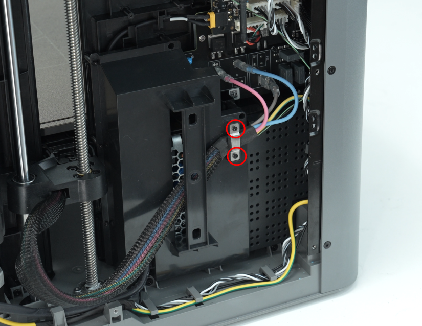
Use an H1.5 hex wrench to remove the five screws securing the AC board cover (BT2×5) in sequence, then take off the AC board cover and set it aside (the heatbed wire does not need to be removed from the power cover) to facilitate later removal of the power supply.


Passo 4: Replace the MC Board Power Cable
Use a Phillips screwdriver to loosen the three screws on the power supply and free the three cables;
Disconnect the connector from the MC board;
Release the cable from the clips and remove it.
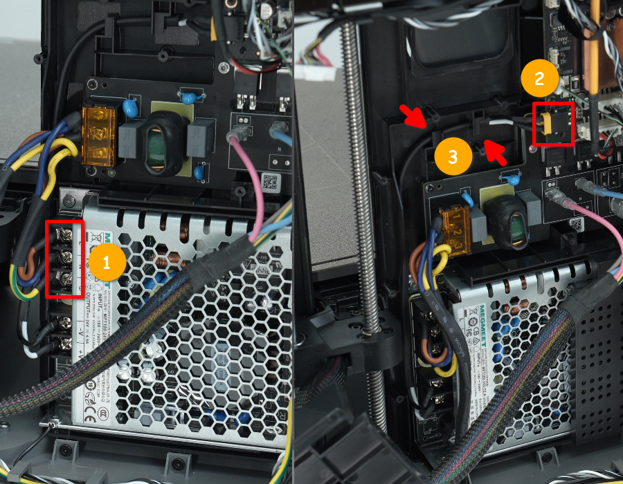
First, connect the new power cable to the MC board’s port.
Following the cable colors in the diagram, connect them to the power supply in order and tighten the screws with a Phillips screwdriver.
Organize the cables neatly.

Reassemble the printer following the procedures and Wiki referenced in Steps 1–3.
Verifying Success
Connect the power, turn on the printer, and perform a function check based on the corresponding connected components.
If you encounter any problems, review the steps and check all connections before trying again. If the problem persists, please contact the Bambu Lab customer service team for further assistance.
Notas Finais
We hope this guide has provided clear and practical support.
If the issue remains unresolved, please submit a support ticket and include your recent printer logs and additional pictures or other details. Our technical team will review your request and provide detailed assistance.
You can also visit Bambu AI, which can instantly answer common questions and provide you with operational guidance.


